How does it work?
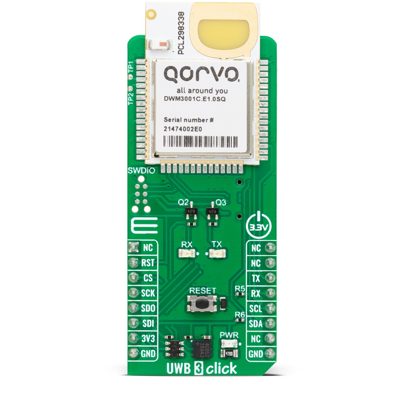
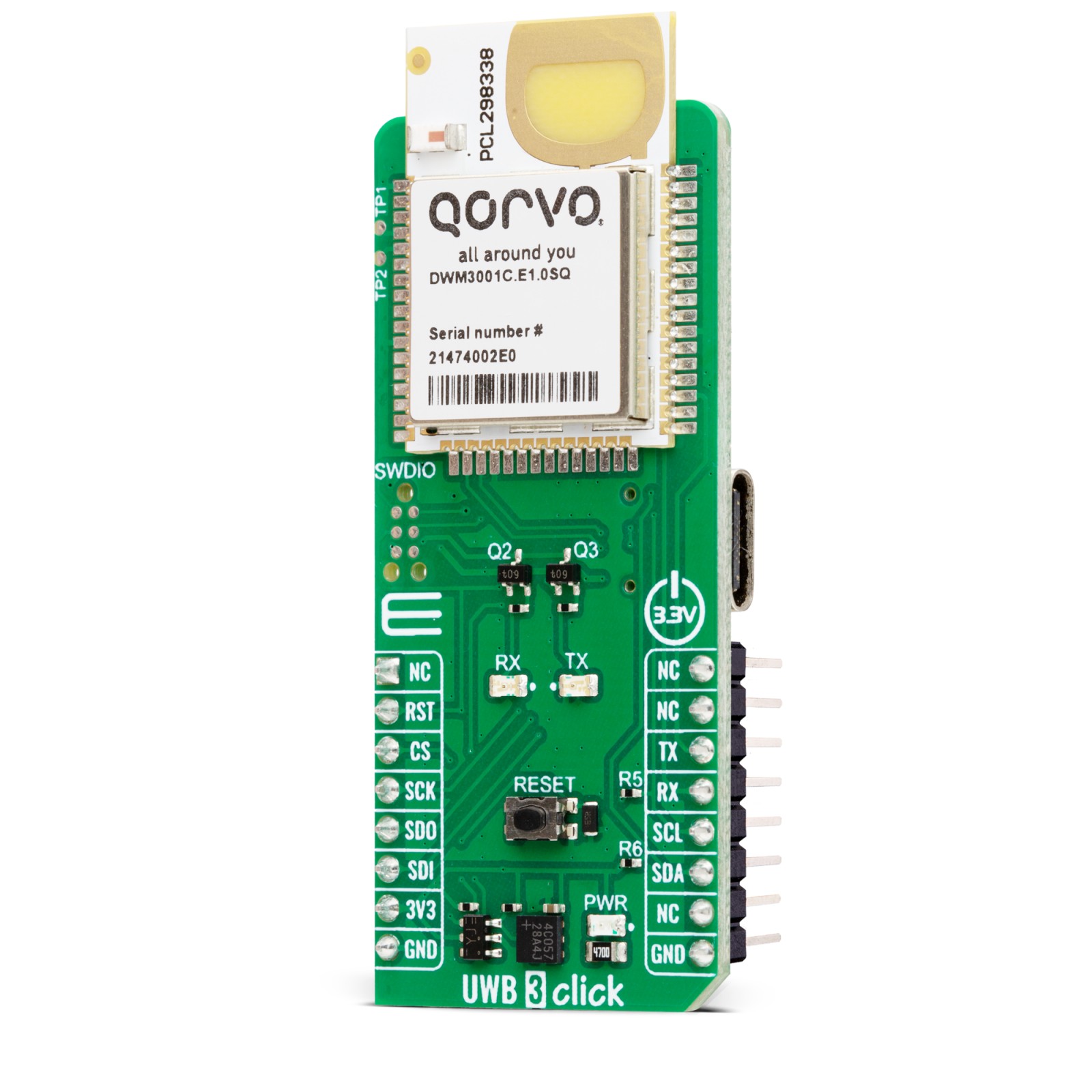
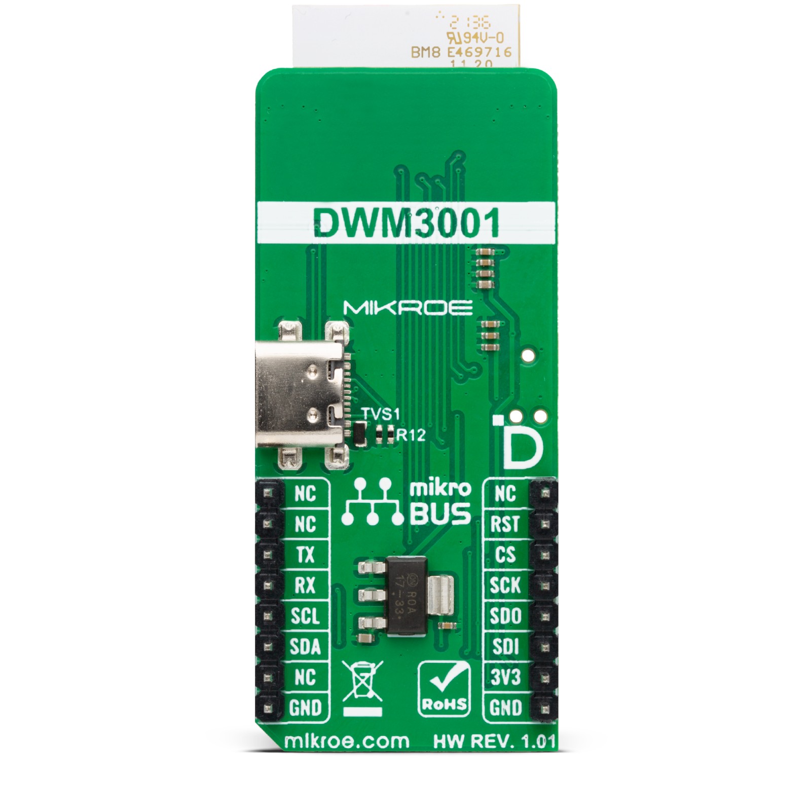
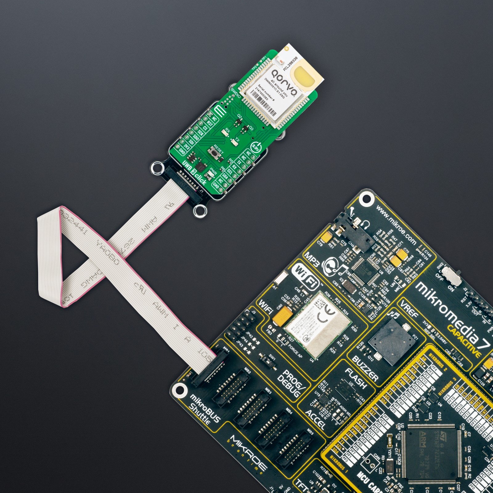
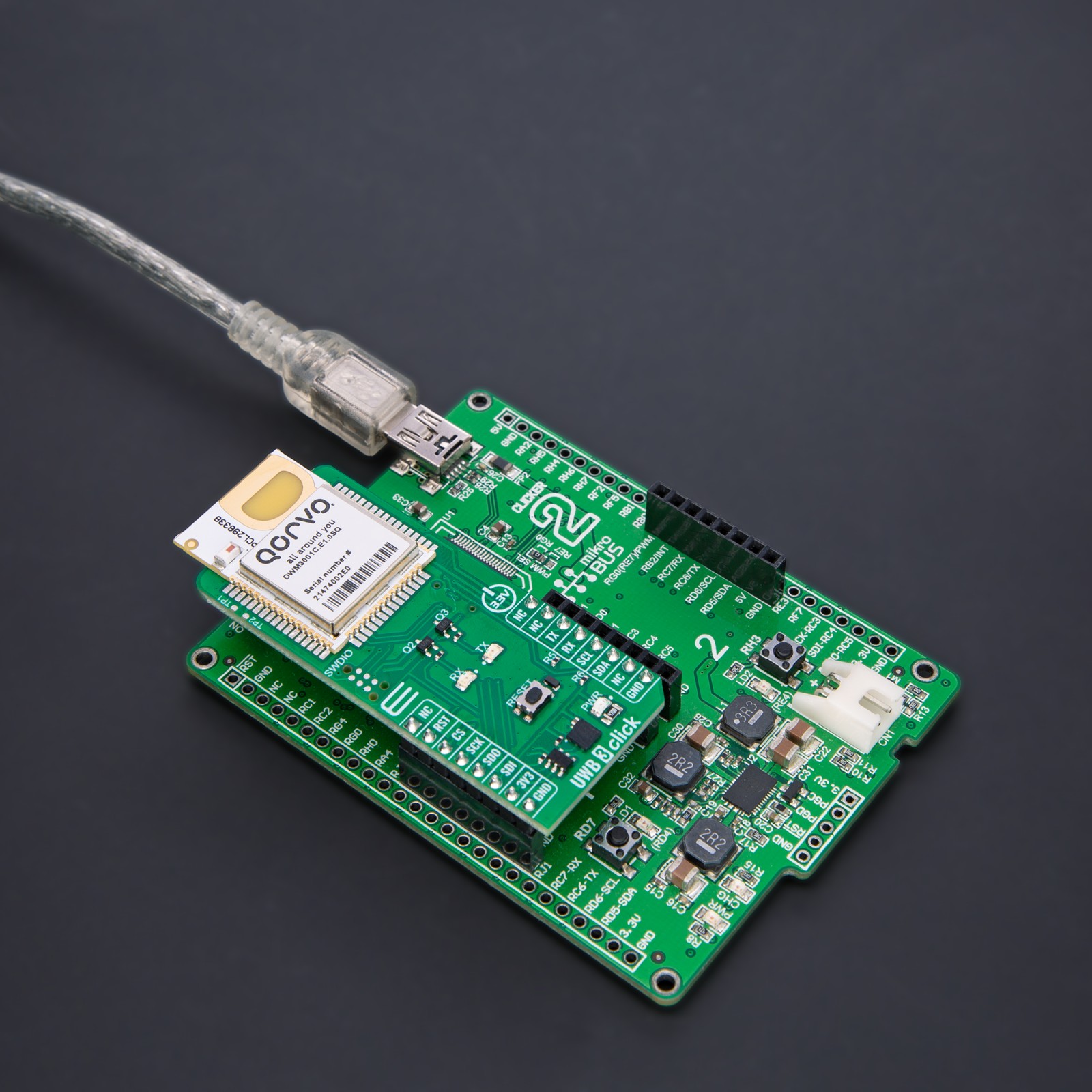
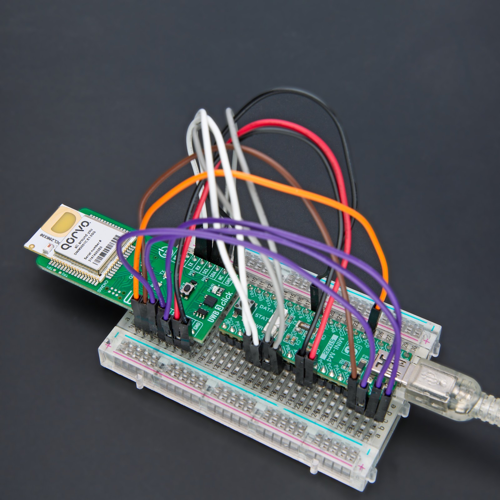
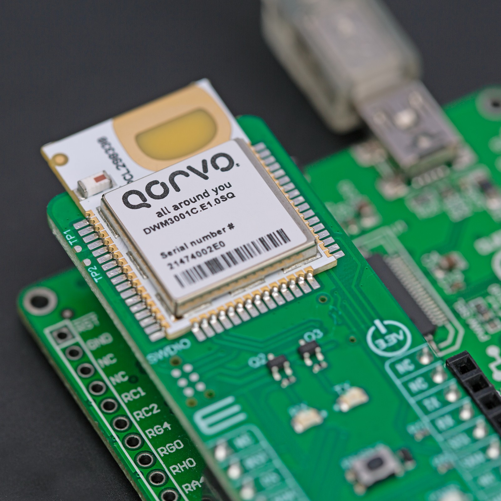
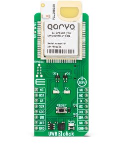
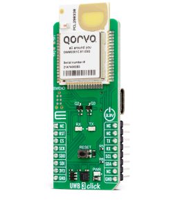
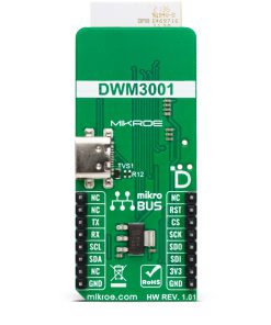
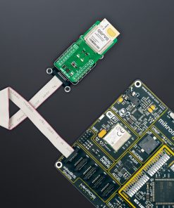
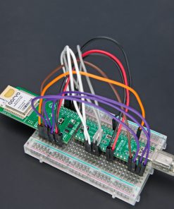
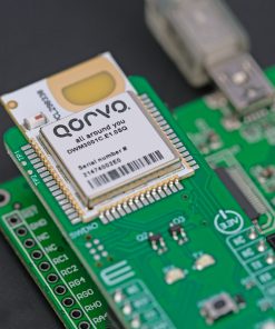
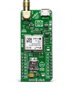
UWB 3 Click is based on the DWM3001, a fully integrated UWB transceiver module from Qorvo. The module can be used in two-way ranging and TDoA applications. It is designed to comply with the FiRa™ PHY and MAC specifications, enabling interoperability with other FiRa™-compliant devices. It supports channels 5 (6.5GHz) and 9 (8GHz) and data rates of 850Kbps up to 6.8Mbps with a maximum packet length of 1023 bytes for high data throughput applications. Besides the planar UWB printed antenna, there is also a Bluetooth chip antenna for an onboard Nordic Cortex-M4 32-bit MCU with 64MHz clock speed for utilizing a BLE radio transceiver. This Nordic MCU is the brain of the module. The nRF52833 has advanced on-chip interfaces, such as NFC-A and USB 2.0 (full-speed 12Mbps), available on UWB 3 Click in a USB C form.
The DWM3001 UWB transceiver also incorporates the LIS12DH, a low-power three-axis linear accelerometer from STMicroelectronics. It is necessary as RTLS tags commonly use accelerometers to initiate UWB ranging only when a tag moves so that battery life can be extended by staying in the lowest power mode by default. Near-field communication type 2 (NFC-A) can be used by adding an NFC antenna to the TP1 and TP2 pads.
UWB 3 Click can use a standard 2-Wire UART interface of the nRF52833 to communicate with the host MCU with commonly used UART RX and TX pins and baud rates of 115200bps. There are RX and TX LEDs for visual presentation of data flow. It can also use a 4-Wire SPI serial interface on 32MHz for communication. The I2C interface, besides the communication with the Nordic MCU, allows you to read the data from the accelerometer. You can reset the module over the RST pin but also over the RESET button. The nRF52833 firmware can be updated over the SWDIO 6-pin needle connector.
NOTE: The current module firmware does not support the SPI and I2C serial interfaces; these interfaces are reserved for future use.
This Click board™ can be operated only with a 3.3V logic voltage level. The board must perform appropriate logic voltage level conversion before using MCUs with different logic levels. Also, this Click board™ comes equipped with a library containing easy-to-use functions and an example code that can be used as a reference for further development.
Specifications
Applications
Can be used for the development of precision real-time location systems (RTLS) using two-way ranging or TDoA schemes in various markets, location-aware wireless sensor networks (WSNs), and more
On-board modules
DWM3001 – fully integrated UWB transceiver module from Qorvo
Key Features
Support IEEE 802.15.4 – 2015, and IEEE 802.15.4z BPRF, fully aligned with FiRaTM PHY, MAC, and certification development, supports channels 5 and 9, Bluetooth, AES-128/256 security block, low power consumption, and more
Interface
I2C,SPI,UART,USB
Feature
ClickID
Compatibility
mikroBUS™
Click board size
L (57.15 x 25.4 mm)
Input Voltage
3.3V
Pinout diagram
This table shows how the pinout on UWB 3 Click corresponds to the pinout on the mikroBUS™ socket (the latter shown in the two middle columns).
Onboard settings and indicators
Label | Name | Default | Description |
---|---|---|---|
LD1 | PWR | – | Power LED Indicator |
LD2 | RX | – | RX LED Indicator |
LD3 | TX | – | TX LED Indicator |
T1 | Reset | – | Reset Button |
UWB 3 Click electrical specifications
Description | Min | Typ | Max | Unit |
---|---|---|---|---|
Supply Voltage | – | 3.3 | – | V |
Operating Frequency | 6250 | – | 8250 | MHz |
Channel Bandwidth | – | 500 | – | MHz |
Data Rates | 850 | – | 6800 | Kbps |
Software Support
We provide a library for the UWB 3 Click as well as a demo application (example), developed using MIKROE compilers. The demo can run on all the main MIKROE development boards.
Package can be downloaded/installed directly from NECTO Studio Package Manager (recommended), downloaded from our LibStock™ or found on Mikroe github account.
Library Description
This library contains API for UWB 3 Click driver.
Key functions
-
uwb3_send_cmd
This function sends a specified command to the click module. -
uwb3_send_cmd_with_parameter
This function sends a command with specified parameter to the click module. -
uwb3_reset_device
This function resets the device by toggling the RST pin state.
Example Description
This example demonstrates the use of an UWB 3 Click board™ by showing the communication between the two click boards.
void application_task ( void )
{
if ( UWB3_OK == uwb3_process( &uwb3 ) )
{
if ( UWB3_OK == uwb3_parse_ranging_block ( ) )
{
uwb3_clear_app_buf( );
}
}
}
The full application code, and ready to use projects can be installed directly from NECTO Studio Package Manager (recommended), downloaded from our LibStock™ or found on Mikroe github account.
Other Mikroe Libraries used in the example:
- MikroSDK.Board
- MikroSDK.Log
- Click.UWB3
Additional notes and informations
Depending on the development board you are using, you may need USB UART click, USB UART 2 Click or RS232 Click to connect to your PC, for development systems with no UART to USB interface available on the board. UART terminal is available in all MIKROE compilers.
mikroSDK
This Click board™ is supported with mikroSDK – MIKROE Software Development Kit. To ensure proper operation of mikroSDK compliant Click board™ demo applications, mikroSDK should be downloaded from the LibStock and installed for the compiler you are using.
For more information about mikroSDK, visit the official page.