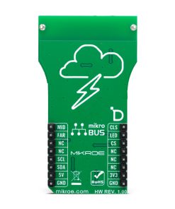
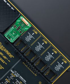
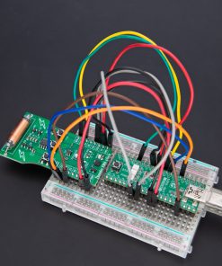
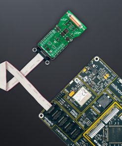
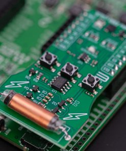
NOTE: This Click board™ is designed to serve as a valuable tool for testing and validating the performance of the AS3935 lightning sensor, which can be found on our Thunder Click board™. Use the emulator to simulate various lightning scenarios, allowing for comprehensive testing and fine-tuning of AS3935’s responsiveness. For more information about Thunder Click, please visit its product page.
How does it work?
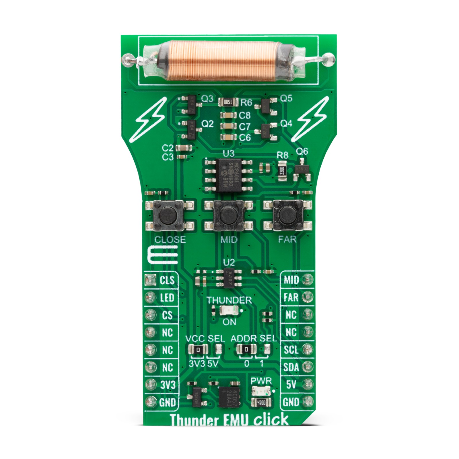
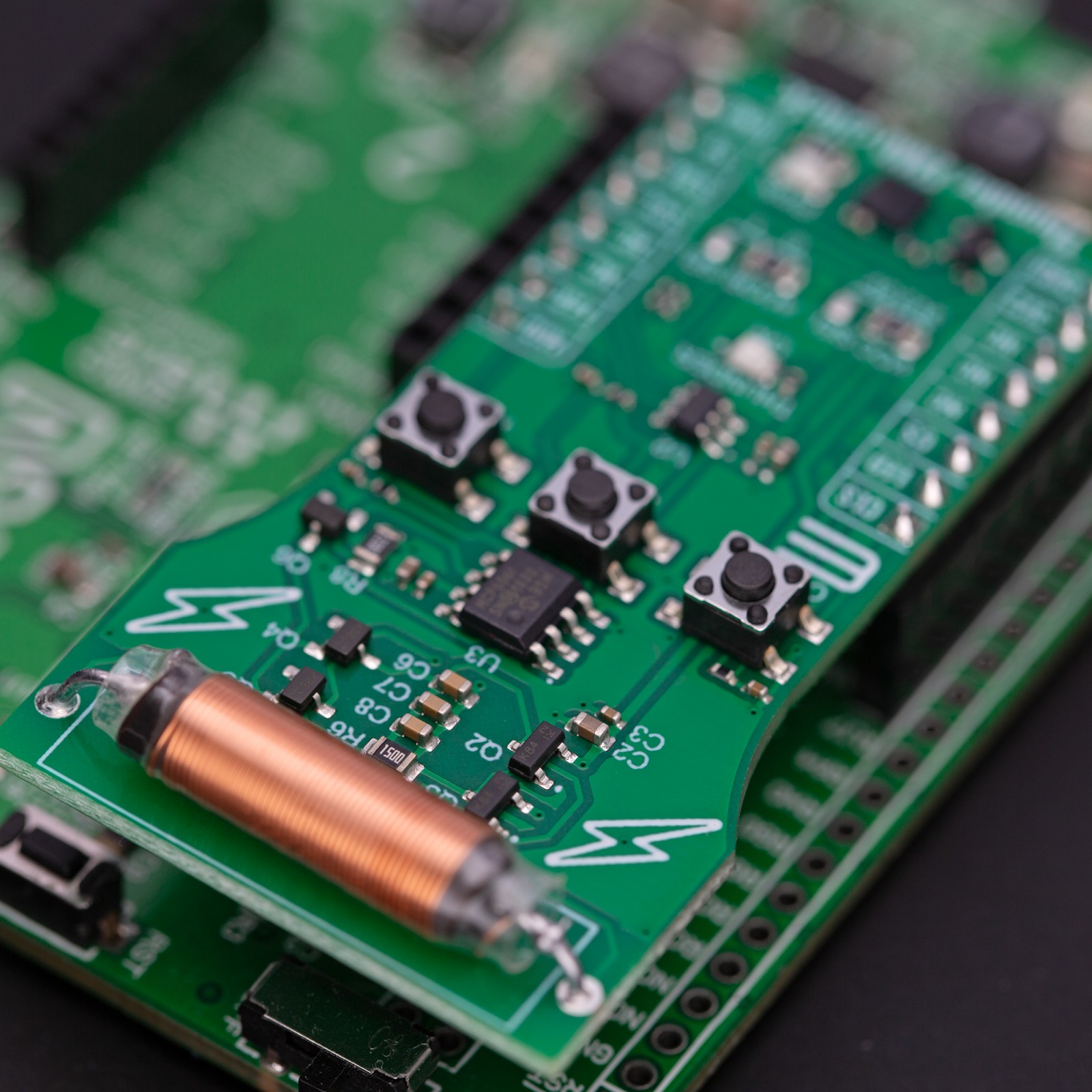
Thunder EMU Click is based on the circuits generating an RF signal miming lightning strikes. The onboard MCP4725 is a 12-bit DAC from Microchip, and it is a precision output amplifier that allows you to achieve rail-to-rail analog output swing. The input and output data can be stored in the EEPROM of the DAC, which in turn enables you to hold the data during power-off time. This analog output of the DAC is then amplified over the MCP606, a CMOS operational amplifier from Microchip. The MCP606 is unity-gain stable with low offset voltage. It also includes rail-to-rail output swing capability. The analog output is then forwarded to the coil of an inductor.
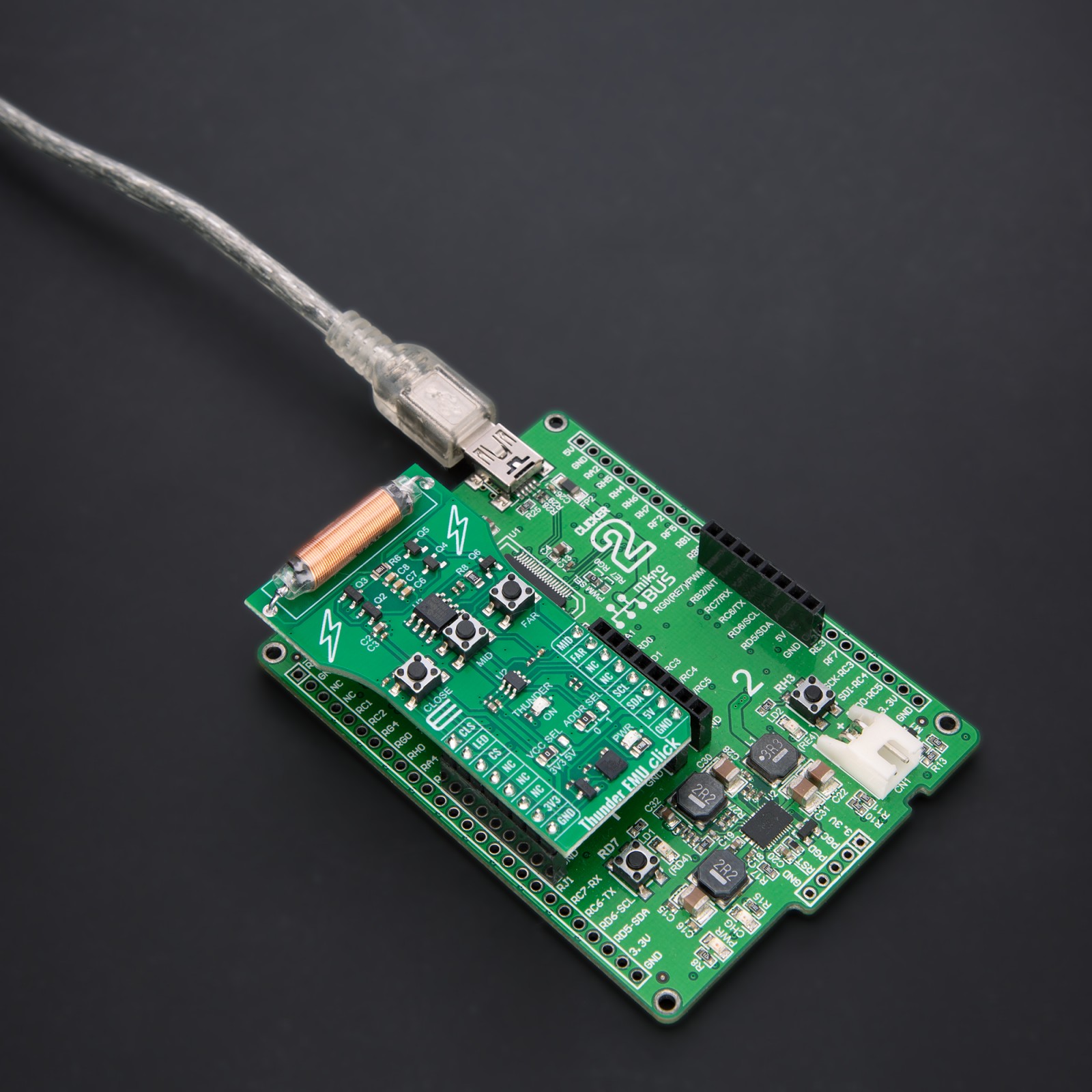
The coil of an inductor mimics a lightning signal on a smaller range than the real lightning will usually do. Of course, the Thunder EMU Click is intended for testing and debugging purposes. No matter what, you can still mimic the different distances of the coming storm lightning. There are three buttons onboard labeled CLOSE, MID, and FAR, which represent mimicking close, mid-range, and far lightning. By combining FAR and MID pressed buttons together, you can select slow-timed lightning strike mode (every 5 minutes), MID and CLOSE together for fast-time lightning stroke mode (every 15 seconds), and all three together for random times lightning strike (from 30 seconds to 30 minutes). The actual „thunder“ of this Click board™ can be „visible“ over the red THUNDER ON LED.
Thunder EMU Click uses a standard 2-Wire I2C interface of the MCO4725 to communicate with the host MCU, supporting standard, fast, and high speeds up to 3.4Mbps. The I2C address can be selected over the ADDR SEL jumper. Pins CLS, MID, and FAR are connected to onboard buttons and have input functions. The LED is an output pin for the THUNDER ON LED.
This Click board™ can operate with either 3.3V or 5V logic voltage levels selected via the VCC SEL jumper. This way, both 3.3V and 5V capable MCUs can use the communication lines properly. Also, this Click board™ comes equipped with a library containing easy-to-use functions and an example code that can be used as a reference for further development.
Specifications
Type
Miscellaneous
Applications
Can be used for debugging the lightning detectors
On-board modules
Circuits that generate an RF signal that mimics lightning strikes
Key Features
Mimic the lightning for testing lightning detectors, three different ranges can be selected (close, mid-range, far), LED for visual presentation, and more
Interface
I2C
Feature
ClickID
Compatibility
mikroBUS™
Click board size
L (57.15 x 25.4 mm)
Input Voltage
3.3V or 5V
Pinout diagram
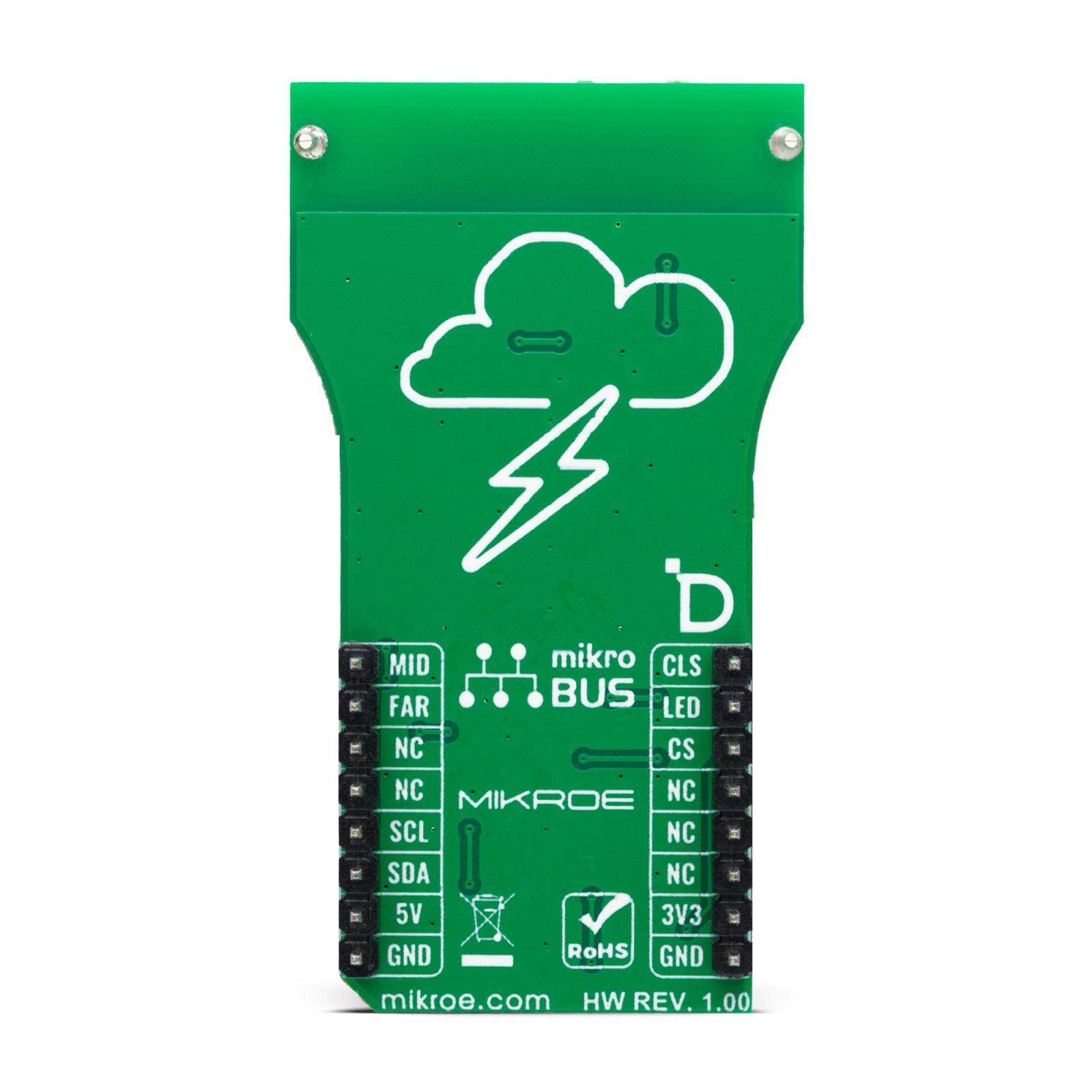
This table shows how the pinout on Thunder EMU Click corresponds to the pinout on the mikroBUS™ socket (the latter shown in the two middle columns).
Onboard settings and indicators
Label | Name | Default | Description |
---|---|---|---|
LD1 | PWR | – | Power LED Indicator |
LD2 | THUNDER ON | – | Active Thunder LED Indicator |
JP1 | VCC SEL | Left | Logic Level Voltage Selection 3V3/5V: Left position 3V3, Right position 5V |
JP2 | ADDR SEL | Left | I2C Address Selection 0/1: Left position 0, Right position 1 |
SW1 | CLOSE | – | Close Button |
SW2 | MID | – | Mid-range Button |
SW3 | FAR | – | Far Button |
Thunder EMU Click electrical specifications
Description | Min | Typ | Max | Unit |
---|---|---|---|---|
Supply Voltage | 3.3 | – | 5 | V |
RF Signal Range | 5 | – | 15 | cm |
Software Support
We provide a library for the Thunder EMU Click as well as a demo application (example), developed using MikroElektronika compilers. The demo can run on all the main MikroElektronika development boards.
Package can be downloaded/installed directly from NECTO Studio Package Manager (recommended), downloaded from our LibStock™ or found on Mikroe github account.
Library Description
This library contains API for Thunder EMU Click driver.
Key functions
-
thunderemu_generate_thunder
This function generates close, mid or far range thunder signal by setting the predefined DAC output profile at the specific timing. -
thunderemu_get_close_pin
This function returns the CLOSE pin logic state. -
thunderemu_get_mid_pin
This function returns the MID pin logic state.
Example Description
This example demonstrates the use of Thunder EMU Click board™ by generating CLOSE, MID, or FAR range thunder signal depending on the click push-buttons state.
void application_task ( void )
{
if ( !thunderemu_get_close_pin ( &thunderemu ) )
{
if ( THUNDEREMU_OK == thunderemu_generate_thunder ( &thunderemu, THUNDEREMU_MODE_CLOSE ) )
{
log_printf( &logger, " Close range thunder signal generated!rnn" );
Delay_ms ( 500 );
}
}
else if ( !thunderemu_get_mid_pin ( &thunderemu ) )
{
if ( THUNDEREMU_OK == thunderemu_generate_thunder ( &thunderemu, THUNDEREMU_MODE_MID ) )
{
log_printf( &logger, " Mid range thunder signal generated!rnn" );
Delay_ms ( 500 );
}
}
else if ( !thunderemu_get_far_pin ( &thunderemu ) )
{
if ( THUNDEREMU_OK == thunderemu_generate_thunder ( &thunderemu, THUNDEREMU_MODE_FAR ) )
{
log_printf( &logger, " Far range thunder signal generated!rnn" );
Delay_ms ( 500 );
}
}
}
The full application code, and ready to use projects can be installed directly from NECTO Studio Package Manager (recommended), downloaded from our LibStock™ or found on Mikroe github account.
Other Mikroe Libraries used in the example:
- MikroSDK.Board
- MikroSDK.Log
- Click.ThunderEMU
Additional notes and informations
Depending on the development board you are using, you may need USB UART click, USB UART 2 Click or RS232 Click to connect to your PC, for development systems with no UART to USB interface available on the board. UART terminal is available in all MikroElektronika compilers.
mikroSDK
This Click board™ is supported with mikroSDK – MikroElektronika Software Development Kit. To ensure proper operation of mikroSDK compliant Click board™ demo applications, mikroSDK should be downloaded from the LibStock and installed for the compiler you are using.
For more information about mikroSDK, visit the official page.