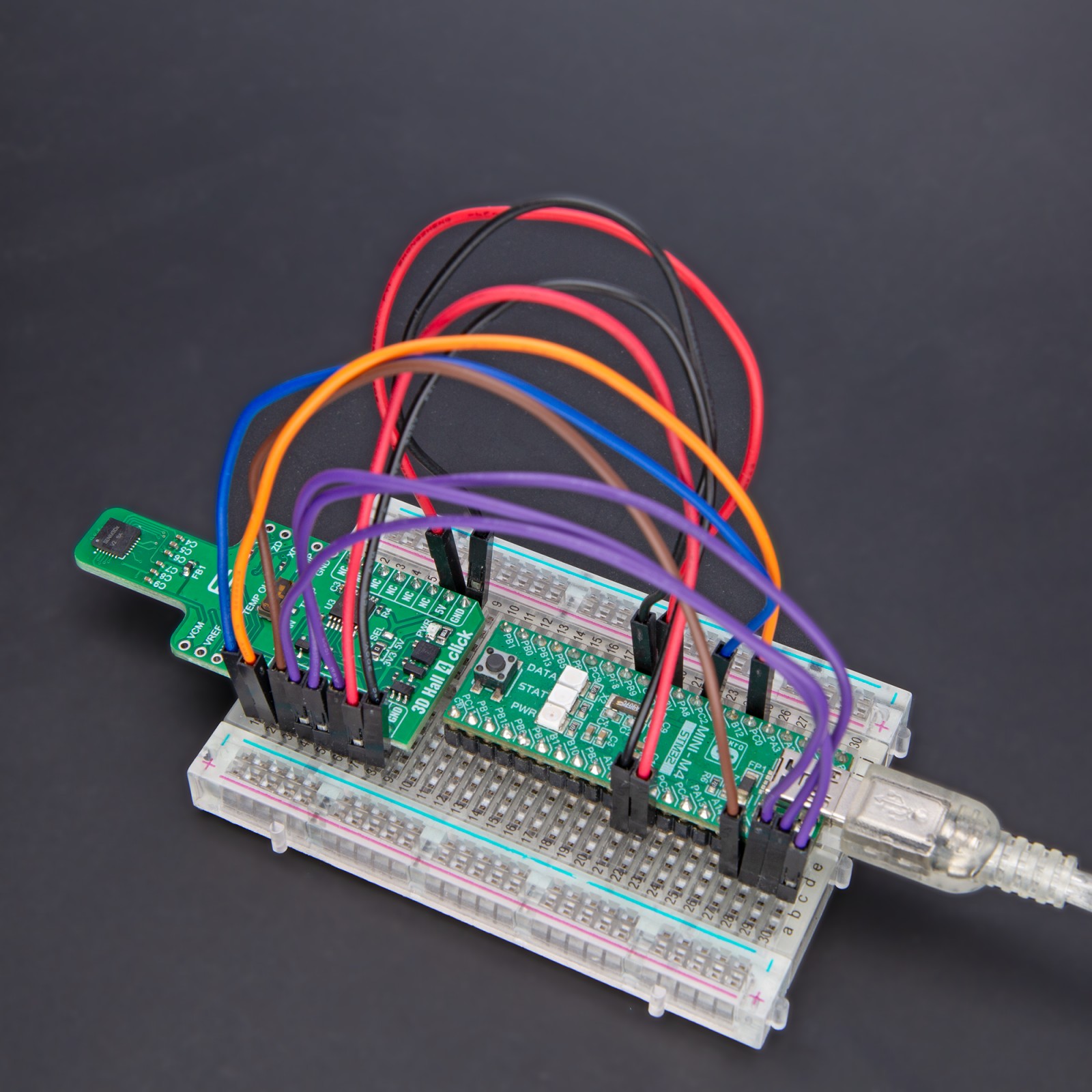
How does it work?
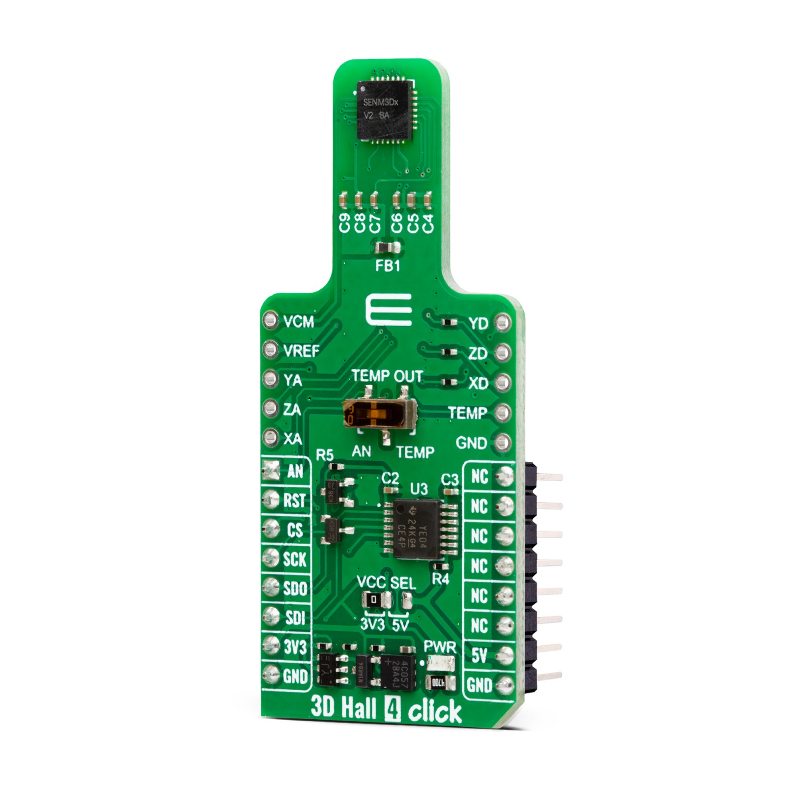
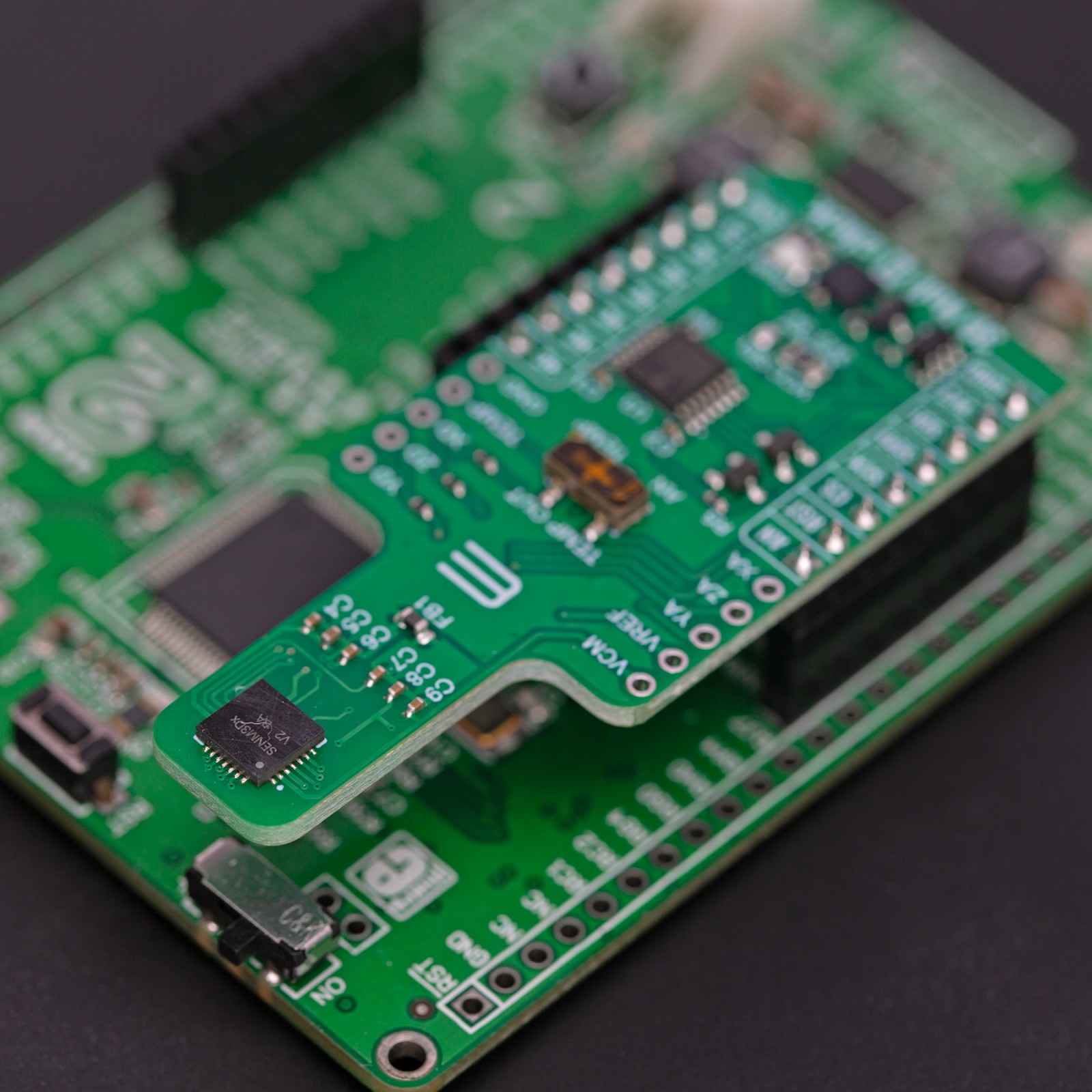
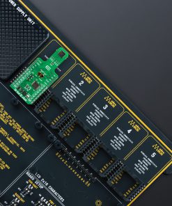
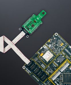
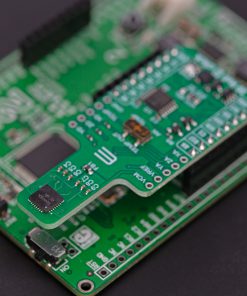
3D Hall 4 Click is based on the SENM3Dx, a 3D Hall magnetic sensor from SENIS. The sensor incorporates three groups of mutually orthogonal Hall-effect elements, of which one is horizontal and two are vertical. Each of them has biasing circuits and amplifiers. Those elements are very compact, allowing for the sensor’s very high spatial resolution. In addition, by incorporating some other techniques, the sensor features high angular accuracy, significantly suppressing offset, low-frequency noise, and the planar Hall effect.
The sensor provides high analog frequency bandwidth from DC to 220kHz and has a built-in temperature sensor that measures the chip temperature. Over the TEMP OUT switch, you can select the host MCU to read the temperature or connect the sensor temperature output to the TEMP connector for testing. There are also two 3-pin headers for analog and digital output of all three magnetic field dimensions. Finally, there is VCM, a virtual ground, and VREF, a bandgap reference voltage pin.
3D Hall Click uses an SPI serial interface to communicate with the host MCU and is compatible with SPI mode 1. The sensor is a 5V device, and to allow 3.3V MCUs to work with the sensor, the 3D Hall Click is equipped with the TXB0104, a 4-bit bidirectional voltage-level translator from Texas Instruments. The temperature output of the sensor, host MCU, can read over the AN pin if selected over the TEMP OUT switch.
This Click board™ can operate with either 3.3V or 5V logic voltage levels selected via the VCC SEL jumper. This way, both 3.3V and 5V capable MCUs can use the communication lines properly. Also, this Click board™ comes equipped with a library containing easy-to-use functions and an example code that can be used as a reference for further development.
Specifications
Type
Magnetic
Applications
Can be used for the development of a wide range of magnetic sensing, including robotics position sensing, angle measurement at the end of the shaft and out-of-shaft configurations, and many more
On-board modules
SENM3Dx – 3D Hall magnetic sensor from SENIS
Key Features
Real 3D magnetic-field measurement, possibility to select the active sensitivity axis, high magnetic field resolution, high analog frequency bandwidth, built-in temperature sensor, on-chip correction of sensitivity, offset, noise, and more
Interface
Analog,SPI
Feature
ClickID
Compatibility
mikroBUS™
Click board size
L (57.15 x 25.4 mm)
Input Voltage
3.3V or 5V
Pinout diagram
This table shows how the pinout on 3D Hall 4 Click corresponds to the pinout on the mikroBUS™ socket (the latter shown in the two middle columns).
Onboard settings and indicators
Label | Name | Default | Description |
---|---|---|---|
LD1 | PWR | – | Power LED Indicator |
JP1 | VCC SEL | Left | Logic Level Voltage Selection 3V3/5V: Left position 3V3, Right position 5V |
SW1 | TEMP OUT | – | Temperature Output Selection AN/TEMP: Left position AN, Right position TEMP |
3D Hall 4 Click electrical specifications
Description | Min | Typ | Max | Unit |
---|---|---|---|---|
Supply Voltage | 3.3 | – | 5 | V |
Measurement Range | 30 | – | 4000 | mT |
Magnetic Field Resolution | – | 1 | – | μT |
Software Support
We provide a library for the 3D Hall 4 Click as well as a demo application (example), developed using MIKROE compilers. The demo can run on all the main MIKROE development boards.
Package can be downloaded/installed directly from NECTO Studio Package Manager (recommended), downloaded from our LibStock™ or found on Mikroe github account.
Library Description
This library contains API for 3D Hall 4 Click driver.
Key functions
-
c3dhall4_read_data
This function reads the measurement status, 3-axes magnetic field data, and the chip internal temperature. -
c3dhall4_reg_write
This function writes a desired number of data bytes starting from the selected register by using SPI serial interface. -
c3dhall4_reg_read
This function reads a desired number of data bytes starting from the selected register by using SPI serial interface.
Example Description
This example demonstrates the use of 3D Hall 4 Click board™ by reading the magnetic field strength from 3 axes and the sensor internal temperature.
void application_task ( void )
{
c3dhall4_data_t data_res;
if ( C3DHALL4_OK == c3dhall4_read_data ( &c3dhall4, &data_res ) )
{
log_printf( &logger, " Status: 0x%.2Xrn", data_res.status );
log_printf( &logger, " X data: %.1f mTrn", data_res.x_data );
log_printf( &logger, " Y data: %.1f mTrn", data_res.y_data );
log_printf( &logger, " Z data: %.1f mTrn", data_res.z_data );
log_printf( &logger, " Chip temperature: %.2f degCrnn", data_res.chip_temp );
Delay_ms ( 1000 );
}
}
The full application code, and ready to use projects can be installed directly from NECTO Studio Package Manager (recommended), downloaded from our LibStock™ or found on Mikroe github account.
Other Mikroe Libraries used in the example:
- MikroSDK.Board
- MikroSDK.Log
- Click.3DHall4
Additional notes and informations
Depending on the development board you are using, you may need USB UART click, USB UART 2 Click or RS232 Click to connect to your PC, for development systems with no UART to USB interface available on the board. UART terminal is available in all MIKROE compilers.
mikroSDK
This Click board™ is supported with mikroSDK – MIKROE Software Development Kit. To ensure proper operation of mikroSDK compliant Click board™ demo applications, mikroSDK should be downloaded from the LibStock and installed for the compiler you are using.
For more information about mikroSDK, visit the official page.