How does it work?
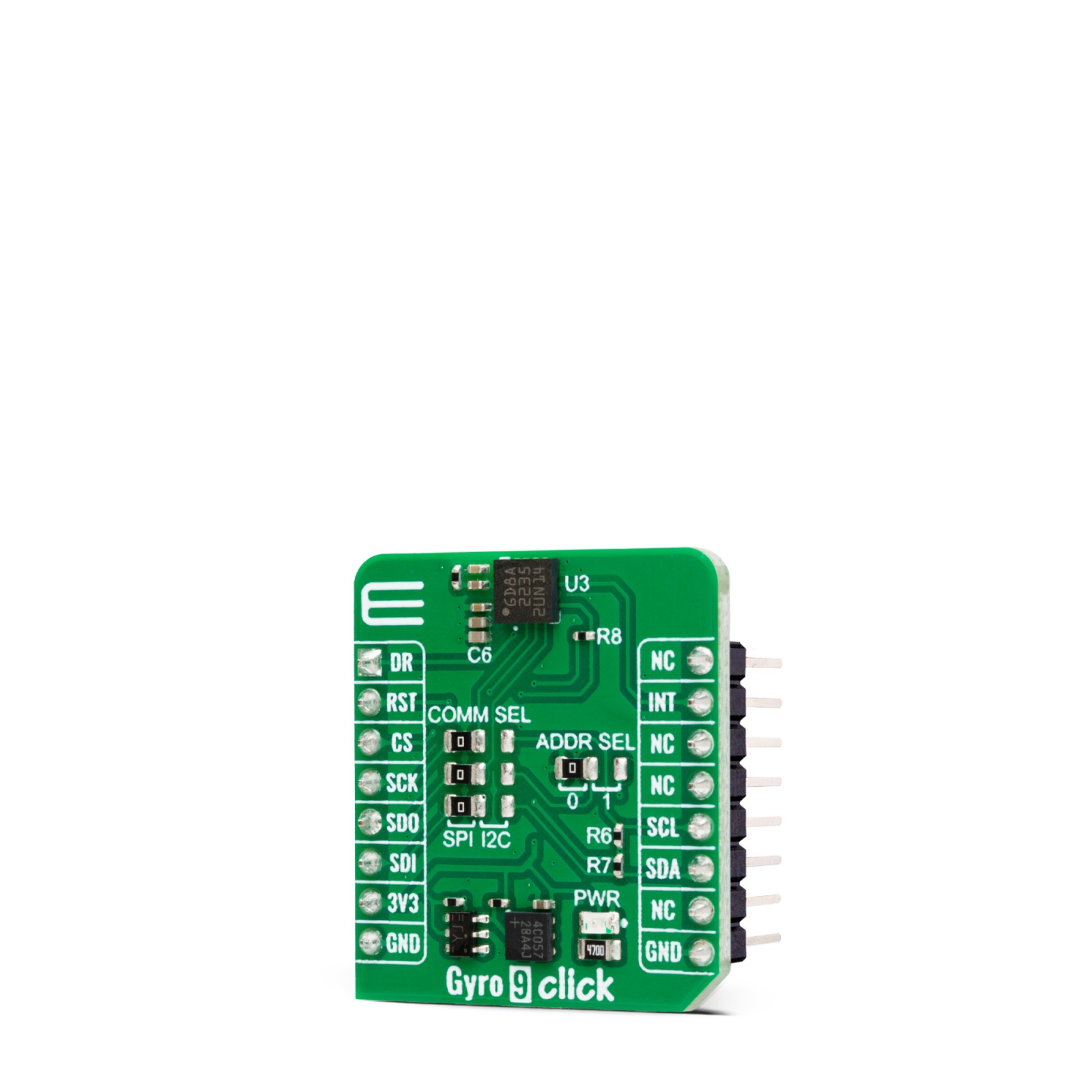
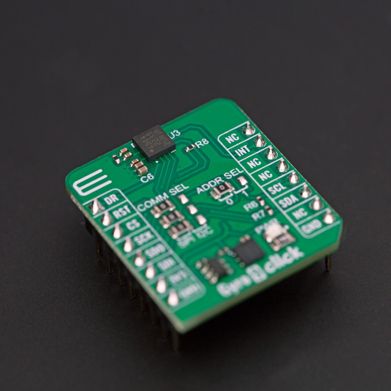
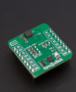
Gyro 9 Click is based on the A3G4250D, a MEMS motion sensor from STMicroelectronics. It includes a sensing element and an IC interface capable of providing the measured angular rate to the host MCU. The sensor has a full scale of ±245dps and can measure rates with a user-selectable bandwidth. The sensor also embeds a 32-slot, 16-bit data FIFO for each of the three output channels: yaw, pitch, and roll. This allows consistent power saving for the system, as the host MCU doesn’t need to poll the data continuously. There is also a Bypass mode, which lets FIFO not operational and empty. The third mode is a Stream mode.
Gyro 9 Click can use both the 4-wire SPI serial interface and the I2C interface to communicate with the host MCU. The selection can be made over the COMM SEL. The SPI is selected by default and supports clock frequency up to 10MHz. The I2C interface supports frequencies up to 400KHz. The I2C address can be selected over the ADDR SEL jumper (0 set by default). The gyroscope can be reset over the RST pin. The INT pin is a programmable interrupt and can be used in a combination of events. The DR is a data-ready output that generates dedicated interrupts depending on FIFO or Stream mode statuses.
This Click board™ can be operated only with a 3.3V logic voltage level. The board must perform appropriate logic voltage level conversion before using MCUs with different logic levels. Also, this Click board™ comes equipped with a library containing easy-to-use functions and an example code that can be used as a reference for further development.
Specifications
Type
Motion
Applications
Can be used for the development of in-dash car navigation, telematics, e-tolling, motion control with MMI (man-machine interface), and more
On-board modules
A3G4250D – MEMS motion sensor from STMicroelectronics
Key Features
Integrates ow and high-pass filters with user-selectable bandwidth, ultra-stable over temperature and time, embedded power-down and sleep mode, embedded temperature sensor, embedded FIFO, high shock survivability, and more
Interface
I2C,SPI
Feature
ClickID
Compatibility
mikroBUS™
Click board size
S (28.6 x 25.4 mm)
Input Voltage
3.3V
Pinout diagram
This table shows how the pinout on Gyro 9 Click corresponds to the pinout on the mikroBUS™ socket (the latter shown in the two middle columns).
Onboard settings and indicators
Label | Name | Default | Description |
---|---|---|---|
LD1 | PWR | – | Power LED Indicator |
JP1-JP2 | COMM SEL | Left | Communication Interface Selection SPI/I2C: Left position SPI, Right position I2C |
JP4 | ADDR SEL | Left | I2C Address Selection 0/1: Left position 0, Right position 1 |
Gyro 9 Click electrical specifications
Description | Min | Typ | Max | Unit |
---|---|---|---|---|
Supply Voltage | – | 3.3 | – | V |
Full-Scale Range | – | ±245 | – | dps |
Sensitivity | 7.4 | 8.75 | 10.1 | mdps/digit |
Software Support
We provide a library for the Gyro 9 Click as well as a demo application (example), developed using MIKROE compilers. The demo can run on all the main MIKROE development boards.
Package can be downloaded/installed directly from NECTO Studio Package Manager (recommended), downloaded from our LibStock™ or found on Mikroe github account.
Library Description
This library contains API for Gyro 9 Click driver.
Key functions
-
gyro9_get_gyro_axis
Gyro 9 get gyro sensor axes function. -
gyro9_get_axis_data
Gyro 9 get gyro data function. -
gyro9_get_data_ready
Gyro 9 get data ready function.
Example Description
This library contains API for Gyro 9 Click driver. The library initializes and defines the I2C and SPI bus drivers to write and read data from registers, as well as the default configuration for reading gyroscope data.
void application_task ( void )
{
gyro9_axis_t gyro_axis;
if ( gyro9_get_data_ready( &gyro9 ) )
{
if ( GYRO9_OK == gyro9_get_gyro_axis( &gyro9, &gyro_axis ) )
{
log_printf( &logger, " Gyro X: %.2f pdsrn", gyro_axis.x );
log_printf( &logger, " Gyro Y: %.2f pdsrn", gyro_axis.y );
log_printf( &logger, " Gyro Z: %.2f pdsrn", gyro_axis.z );
log_printf( &logger, "_________________rn" );
Delay_ms( 1000 );
}
}
}
The full application code, and ready to use projects can be installed directly from NECTO Studio Package Manager (recommended), downloaded from our LibStock™ or found on Mikroe github account.
Other Mikroe Libraries used in the example:
- MikroSDK.Board
- MikroSDK.Log
- Click.Gyro9
Additional notes and informations
Depending on the development board you are using, you may need USB UART click, USB UART 2 Click or RS232 Click to connect to your PC, for development systems with no UART to USB interface available on the board. UART terminal is available in all MIKROE compilers.
mikroSDK
This Click board™ is supported with mikroSDK – MIKROE Software Development Kit. To ensure proper operation of mikroSDK compliant Click board™ demo applications, mikroSDK should be downloaded from the LibStock and installed for the compiler you are using.
For more information about mikroSDK, visit the official page.