How does it work?
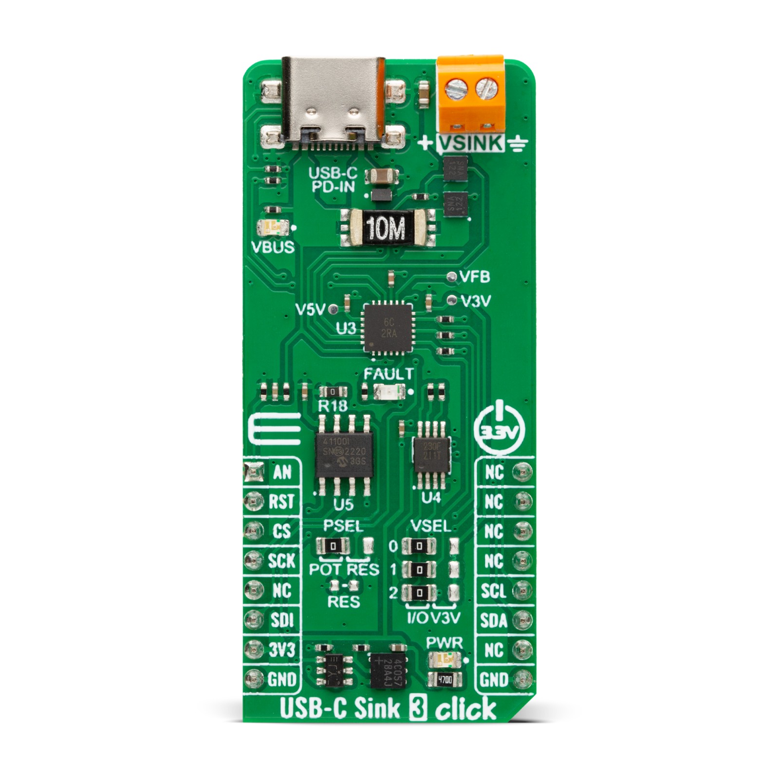
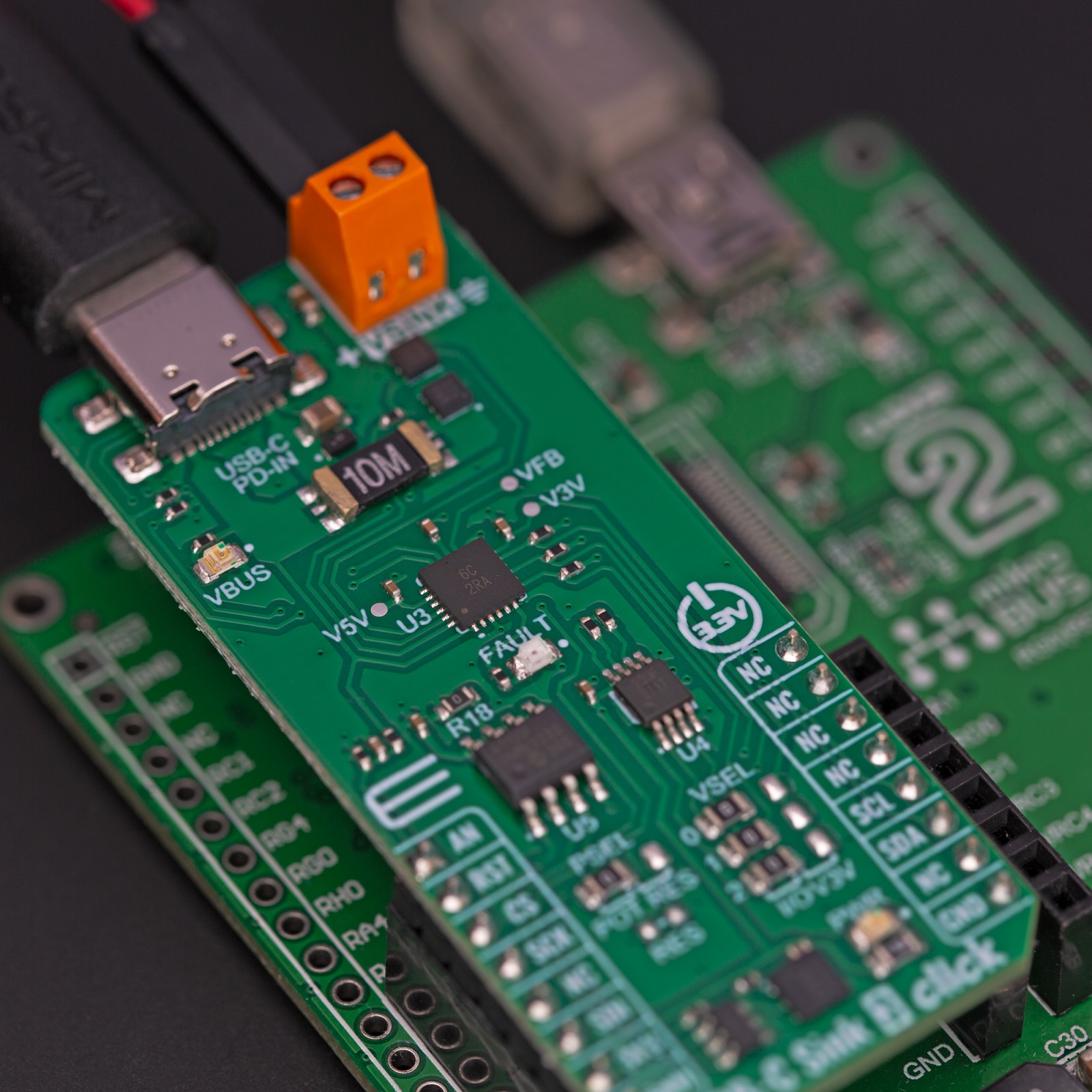
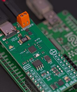
USB-C Sink 3 Click is based on the AP33771, a high-performance USB PD sink controller from Diodes Incorporated. It supports up to eight voltage selections alongside ten different power ranges selection. In addition to selected voltages, both fixed PDO and PPS APDO in the PD source adapter are supported in the AP33771 search algorithm. The PD controller supports OVP with auto-restart, one-time programming (OTP) ROM for main firmware, and power capability selection. The onboard FAULT LED serves as a visual presentation of the negotiation mismatch.
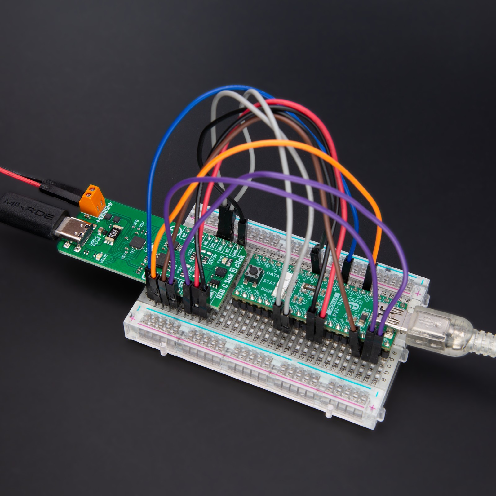
USB-C Sink 3 Click is equipped with a VSINK, an external power supply terminal that comes with a pair of MOSFETs, according to the AP33771’s driver for N-MOS VBUS power switch support. The PD controller can control the external NMOS switch ON or OFF. The USB-C connector acts as a PD-IN discharge path terminal with a USB Type-C configuration channels 1 and 2. The presence of the power supply on the USB C is indicated over the VBUS LED.
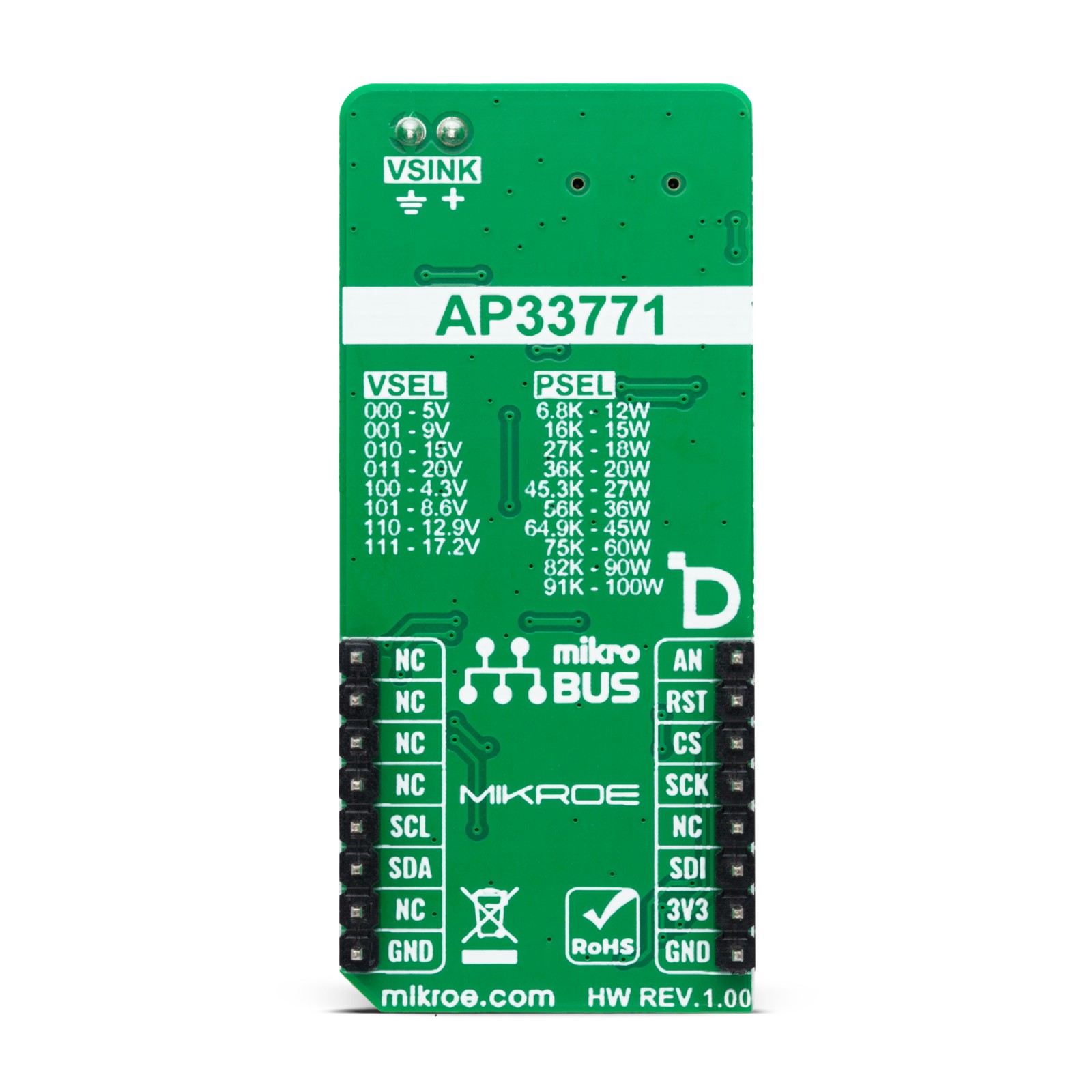
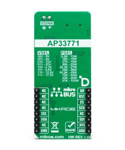
The USB-C Sink 3 Click comes with a VSEL three 2-position jumpers labeled 0, 1, and 2 to select the desired target voltage. There are I/O and FIX(ed) sides which allow you to choose between hardware and software target voltage selection in eight positions and a target voltage range from 5V up to 17.2V. The VSEL is set to I/O by default, where you can set logic states to the three IO pins over the TCA9536, a remote 4-bit I2C, and SMBus I/O expander with configuration registers from Texas Instruments. The table of the combination of the positions and the resulting target voltages is printed at the bottom of the Click board™. You can use fixed jumper positions by setting the jumpers as you like, where I/O acts as a 0 and 3V3 as a 1 position. The 5V and 3.3V LDO voltage output can be measured over the V5V and V3V pads, and voltage feedback over the VFB pad.
To select the desired power, there is the MCP41100T, a digital potentiometer with an SPI interface from Microchip. By selecting the corresponding resistance value on the digital potentiometer, you can choose one of the current capabilities ranging from 12W to 100W. The table with the expected resistance and the resulting current is printed at the bottom of the Click board™. In addition, you can solder a standard resistor by soldering it on RES resistor pads. For that purpose, you should set the PSEL jumper to a RES position, as it is set to a POT position by default.
USB-C Sink 3 Click uses a standard 2-Wire I2C interface of the MCP41100T to communicate with the host MCU. One of the main features of the USB-C Sink 3 Click is the ability to track the VBUS voltage over the AN pin of the mikroBUS™ socket.
This Click board™ can be operated only with a 3.3V logic voltage level. The board must perform appropriate logic voltage level conversion before using MCUs with different logic levels. Also, it comes equipped with a library containing functions and an example code that can be used, as a reference, for further development.
Specifications
Type
USB-C PD
Applications
Can be used for the USB Type-C connector-equipped battery-powered devices or DC-power input devices, USB PD3.0 PPS testers, and more
On-board modules
AP33771 – high-performance USB PD sink controller from Diodes Incorporated
Key Features
Large voltage operating range, compliant with USB PD rev3.0 V1.2, power capability selection, PD sink controller, supports PPS, OTP, supports OVP, supports dead-battery mode, testing pads, and more
Interface
I2C,SPI
Feature
ClickID
Compatibility
mikroBUS™
Click board size
L (57.15 x 25.4 mm)
Input Voltage
3.3V
Pinout diagram
This table shows how the pinout on USB-C Sink 3 Click corresponds to the pinout on the mikroBUS™ socket (the latter shown in the two middle columns).
Onboard settings and indicators
Label | Name | Default | Description |
---|---|---|---|
LD1 | PWR | – | Power LED Indicator |
LD2 | VBUS | – | VBUS LED Indicator |
LD3 | FAULT | – | Negotiation Mismatch Fault LED Indicator |
VSEL0-VSEL2 | VSEL | Left | Voltage Selection I/O / 3V3: Left position I/O, Right position 3V3 |
PSEL0 | PSEL | Left | Power Selection POT/RES: Left position POT, Right position RES |
USB-C Sink 3 Click electrical specifications
Description | Min | Typ | Max | Unit |
---|---|---|---|---|
Supply Voltage | – | 3.3 | – | V |
USB Input Voltage | – | 5 | – | V |
Voltage Selection | 5 | – | 17.2 | V |
Power Selection | 12 | – | 100 | W |
Software Support
We provide a library for the USB-C Sink 3 Click as well as a demo application (example), developed using MIKROE compilers. The demo can run on all the main MIKROE development boards.
Package can be downloaded/installed directly from NECTO Studio Package Manager(recommended), downloaded from our LibStock™ or found on Mikroe github account.
Library Description
This library contains API for USB-C Sink 3 Click driver.
Key functions
-
usbcsink3_set_voltage
USB-C Sink 3 set the voltage function. -
usbcsink3_set_power
USB-C Sink 3 set the power function. -
usbcsink3_get_vbus
USB-C Sink 3 get VBUS function.
Example Description
This example demonstrates the use of USB-C Sink 3 Click board™ by setting DC power requests and control for Type-C connector-equipped devices (TCD).
void application_task ( void )
{
static float voltage = 0.0;
if ( ( USBCSINK3_OK == usbcsink3_set_voltage( &usbcsink3, USBCSINK3_VTG_SEL_5V ) ) &&
( USBCSINK3_OK == usbcsink3_set_power( &usbcsink3, USBCSINK3_PWR_SEL_15W ) ) )
{
log_printf( &logger, " Output:rnVoltage: 5.0 [V]rnPower: 15.0 [W]rn" );
log_printf( &logger, " - - - - - - - - - - - -rn" );
Delay_ms( 1000 );
usbcsink3_get_vbus ( &usbcsink3, &voltage );
log_printf( &logger, " VBUS : %.1f [V]rn", voltage );
log_printf( &logger, " ------------------------rn" );
Delay_ms( 5000 );
}
if ( ( USBCSINK3_OK == usbcsink3_set_voltage( &usbcsink3, USBCSINK3_VTG_SEL_9V ) ) &&
( USBCSINK3_OK == usbcsink3_set_power( &usbcsink3, USBCSINK3_PWR_SEL_18W ) ) )
{
log_printf( &logger, " Output:rnVoltage: 9.0 [V]rnPower: 18.0 [W]rn" );
log_printf( &logger, " - - - - - - - - - - - -rn" );
Delay_ms( 1000 );
usbcsink3_get_vbus ( &usbcsink3, &voltage );
log_printf( &logger, " VBUS : %.1f [V]rn", voltage );
log_printf( &logger, " ------------------------rn" );
Delay_ms( 5000 );
}
}
The full application code, and ready to use projects can be installed directly from NECTO Studio Package Manager(recommended), downloaded from our LibStock™ or found on Mikroe github account.
Other Mikroe Libraries used in the example:
- MikroSDK.Board
- MikroSDK.Log
- Click.USBCSink3
Additional notes and informations
Depending on the development board you are using, you may need USB UART click, USB UART 2 Click or RS232 Click to connect to your PC, for development systems with no UART to USB interface available on the board. UART terminal is available in all MIKROE compilers.
mikroSDK
This Click board™ is supported with mikroSDK – MIKROE Software Development Kit. To ensure proper operation of mikroSDK compliant Click board™ demo applications, mikroSDK should be downloaded from the LibStock and installed for the compiler you are using.
For more information about mikroSDK, visit the official page.