How does it work?
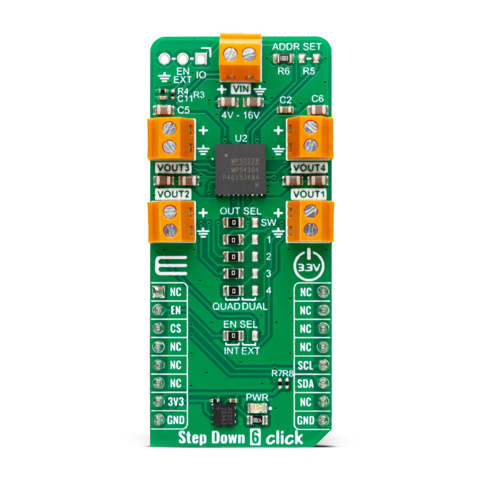
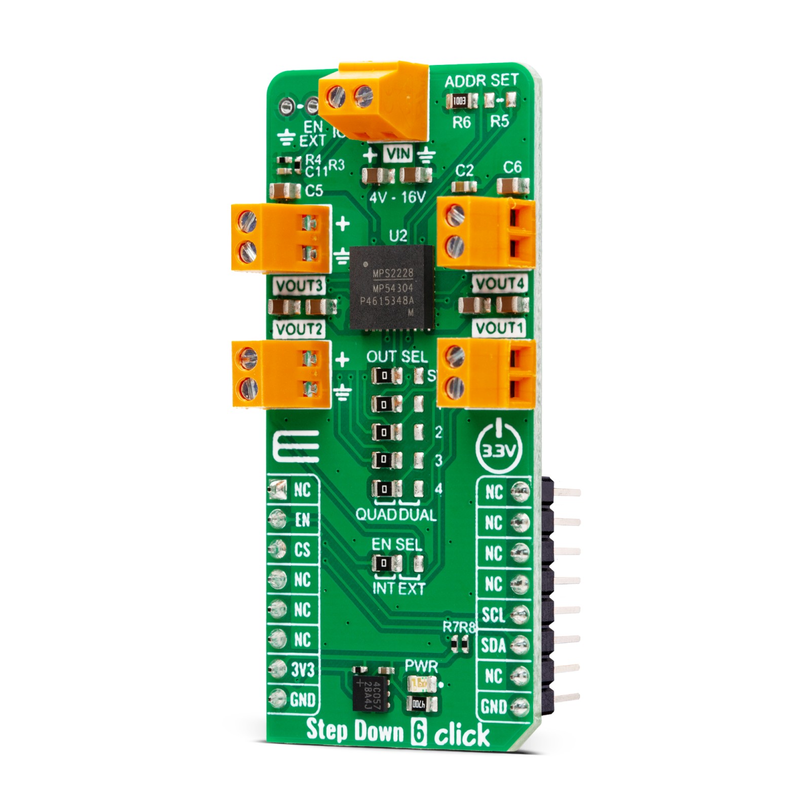
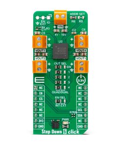
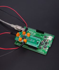
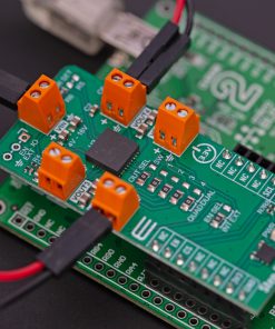
Step Down 6 Click is based on the MPM54304, a quad-output power module from Monolithic Power Systems (MPS). This IC operates over a 4V to 16V input voltage range that can be supplied over the VIN screw terminal. It can step down input voltages as output voltages from 0.55V to 5.4V. The user can choose between straight or parallel output depending on the used output channels, from VOUT1 to VOUT4. Channels VOUT1 and VOUT2 can be paralleled to provide up to 6A of current, and channels VOUT3 and VOUT4 can be paralleled to provide up to 4A of current. The selection between quad and dual channel outputs can be set via the OUT SEL jumpers, where QUAD is selected by default. The user must set all five jumpers into the proper position for the output to work correctly.
The MPM54304 has internal auto-compensation, which eliminates the need for an external compensation network, employs a constant-on-time (COT) control scheme to provide ultra-fast load transient responses, and minimizes the required output capacitance. It also features a two-time non-volatile programmable memory for storing register settings. Using the host MCU, users can set switching frequency, output voltage, over-current and over-voltage protection thresholds, power-on, power-off sequencing, and Forced PWM or Auto-PWM/PFM.
Step Down 6 Click uses a standard 2-Wire I2C interface to communicate with the host MCU, supporting clock frequency up to 3.4MHz and ADDR SET jumper to set the I2C address. In addition to being enabled via the EN pin of the mikroBUS™ socket, the MPM54304 can also be enabled with the appearance of an external power supply by setting the EN SEL jumper to the appropriate position. For that to be done, the EN SEL jumper must be set to the EXT position, thus losing the enable function over the EN pin of the mikroBUS™ socket.
The ADDR SET jumper actually uses the GPIO pin of the MPM54304, which can also be used for other purposes, as it is an input/output pin. This pin can be configured as a Power-Good (PG) pin over the unpopulated IO header that will go to a LOW logic state if any enabled regulator falls below the under-voltage threshold or when all regulators are disabled. It can also be used in the Output Port mode, where it will output corresponding logic depending on the related register. Finally, it can also be used in the SYNCO mode, where it will become the sync output allowing users to phase-shift the clock output to sync another device’s switching frequency.
This Click board™ can be operated only with a 3.3V logic voltage level. The board must perform appropriate logic voltage level conversion before using MCUs with different logic levels. Also, it comes equipped with a library containing functions and an example code that can be used, as a reference, for further development.
Specifications
Type
Buck
Applications
Can be used for the development of FPGA power supplies, multi-rail power systems, MCU/DSP power supplies, and more
On-board modules
MPM54304 – quad-output power module from Monolithic Power Systems (MPS)
Key Features
Wide operating range, wide output range, straight and parallel continuous current output, interleaved operation, configurable multi-functional GPIO pin, configurable paralleling, switching frequency, output voltage, over-current, and over-voltage thresholds, power-on and power-off sequencing, Forced PWM or Auto-PWM/PFM, and more
Interface
I2C
Feature
ClickID
Compatibility
mikroBUS™
Click board size
L (57.15 x 25.4 mm)
Input Voltage
3.3V,External
Pinout diagram
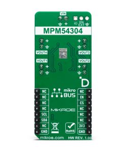
This table shows how the pinout on Step Down 6 Click corresponds to the pinout on the mikroBUS™ socket (the latter shown in the two middle columns).
Onboard settings and indicators
Label | Name | Default | Description |
---|---|---|---|
LD1 | PWR | – | Power LED Indicator |
JP1 | EN SEL | Left | Enable/Sync Selection INT/EXT: Left position INT , Right position EXT |
– | OUT SEL | Right | Output Selection QUAD/DUAL: Left position QUAD, Right position DUAL |
R5-R6 | ADDR SET | R6 Populated | I2C Address Selection / Multi-function I/O |
Step Down 6 Click electrical specifications
Description | Min | Typ | Max | Unit |
---|---|---|---|---|
Supply Voltage | – | 3.3 | – | V |
External Supply Voltage | 4 | – | 16 | V |
Output Voltage | 0.55 | – | 5.4 | V |
Output Current | 2 | – | 6 | A |
Software Support
We provide a library for the Step Down 6 Click as well as a demo application (example), developed using MikroElektronika compilers. The demo can run on all the main MikroElektronika development boards.
Package can be downloaded/installed directly from NECTO Studio Package Manager (recommended), downloaded from our LibStock™ or found on Mikroe github account.
Library Description
This library contains API for Step Down 6 Click driver.
Key functions
-
stepdown6_set_en_pin
Step Down 6 set EN pin state function. -
stepdown6_write_reg
Step Down 6 Register writing function. -
stepdown6_set_out_voltage
Step Down 6 Set output voltage function.
Example Description
This library contains API for the Step Down 6 Click driver. This driver provides the functions to set the output voltage threshold.
void application_task ( void )
{
err_t error_flag = STEPDOWN6_OK;
for ( uint16_t n_cnt = STEPDOWN6_MIN_VOUT_VAL; n_cnt <= STEPDOWN6_MAX_VOUT_VAL; n_cnt += STEPDOWN6_INCREMENT_VOUT_VAL )
{
error_flag |= stepdown6_set_out_voltage( &stepdown6, STEPDOWN6_SELECT_VOUT1, n_cnt );
error_flag |= stepdown6_set_out_voltage( &stepdown6, STEPDOWN6_SELECT_VOUT2, n_cnt );
error_flag |= stepdown6_set_out_voltage( &stepdown6, STEPDOWN6_SELECT_VOUT3, n_cnt );
error_flag |= stepdown6_set_out_voltage( &stepdown6, STEPDOWN6_SELECT_VOUT4, n_cnt );
log_printf( &logger, " Set voltage : %d mV rn", n_cnt );
Delay_ms( 5000 );
}
}
The full application code, and ready to use projects can be installed directly from NECTO Studio Package Manager (recommended), downloaded from our LibStock™ or found on Mikroe github account.
Other Mikroe Libraries used in the example:
- MikroSDK.Board
- MikroSDK.Log
- Click.StepDown6
Additional notes and informations
Depending on the development board you are using, you may need USB UART click, USB UART 2 Click or RS232 Click to connect to your PC, for development systems with no UART to USB interface available on the board. UART terminal is available in all MikroElektronika compilers.
mikroSDK
This Click board™ is supported with mikroSDK – MikroElektronika Software Development Kit. To ensure proper operation of mikroSDK compliant Click board™ demo applications, mikroSDK should be downloaded from the LibStock and installed for the compiler you are using.
For more information about mikroSDK, visit the official page.