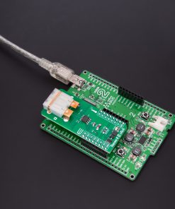
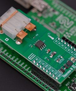
How does it work?
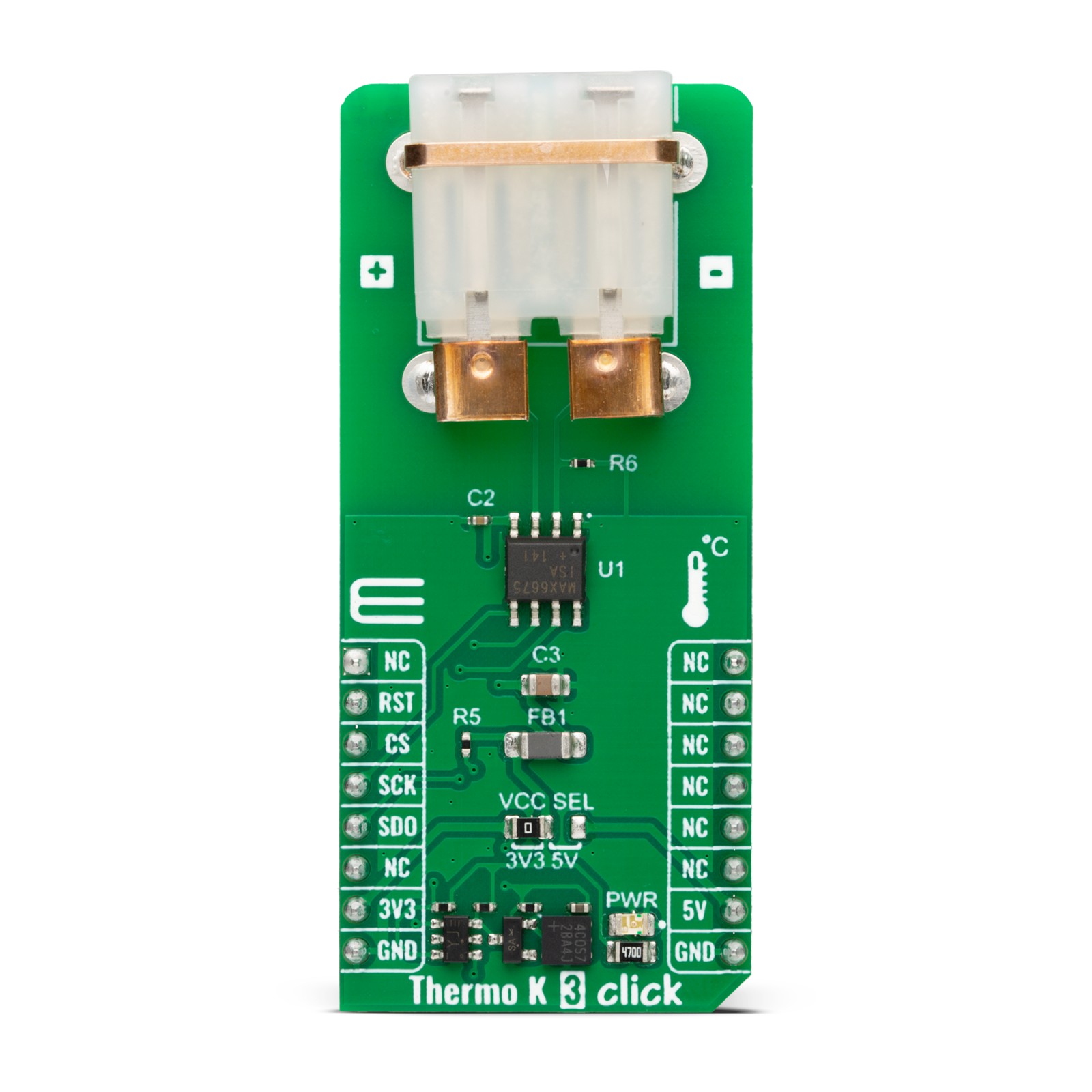
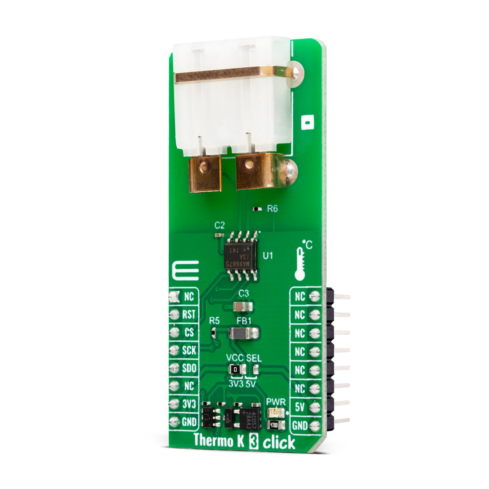
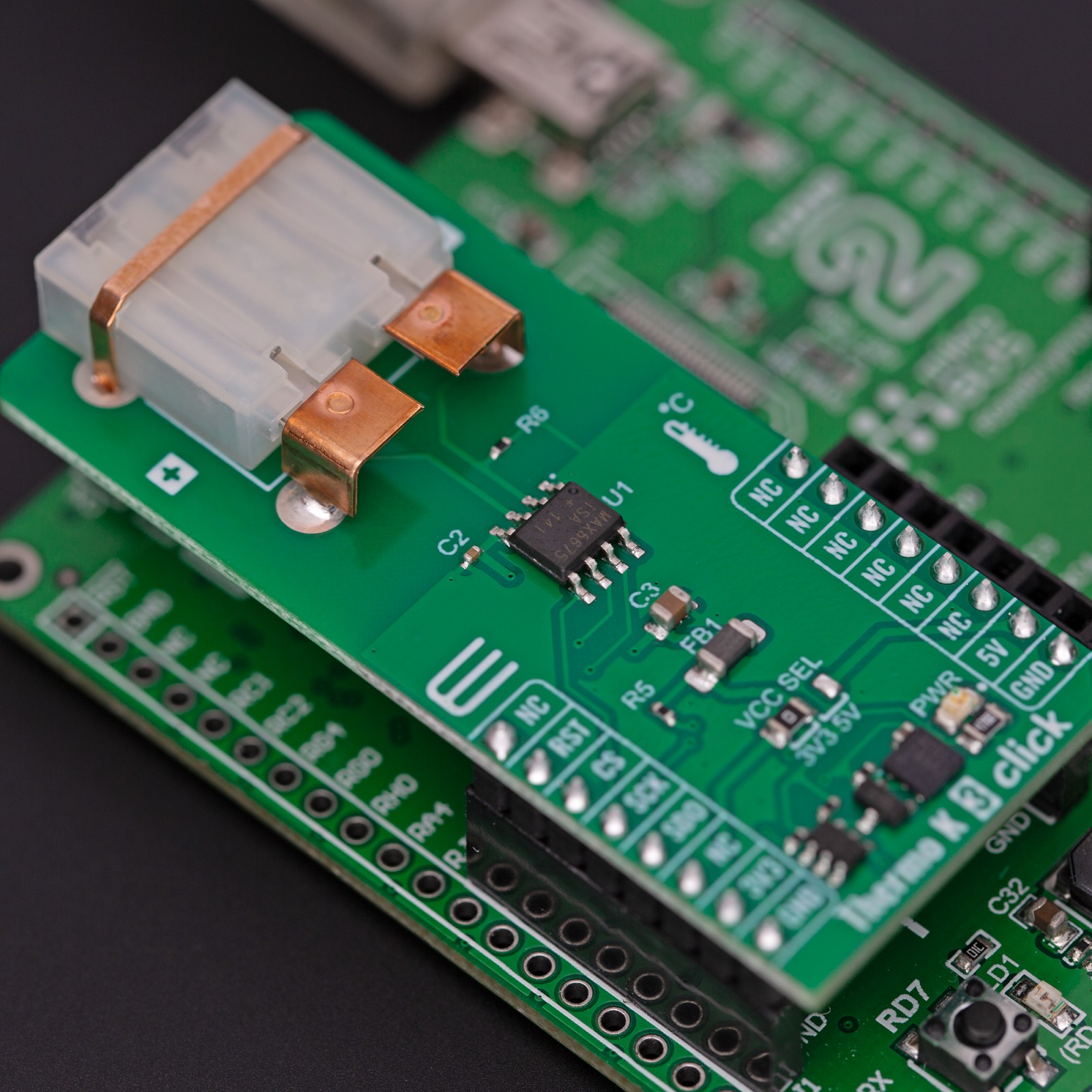
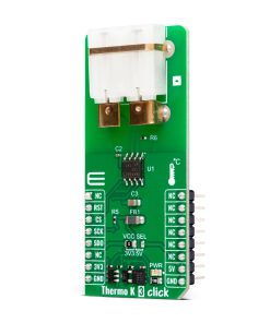
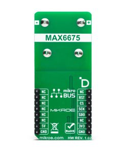
Thermo K 3 Click is based on the MAX6675, a cold-junction-compensated K-thermocouple-to-digital converter from Analog Devices. It includes signal-conditioning hardware to convert the thermocouple signal into a voltage compatible with the input channels of the ADC. The thermocouple circuit consists of two ends of the thermocouple wires, the hot junction, which is the thermocouple probe itself (0°C – 102.75°C), and the cold junction, which is the ambient temperature, usually the board itself (-20°C – 85°C). The MAX6675 senses the difference and corrects for the changes between those two ends by compensating cold junction. The MAX6675 measures the voltage from the thermocouple’s output and the sensing diode and passes it to the internal conversion function stored in the ADC.
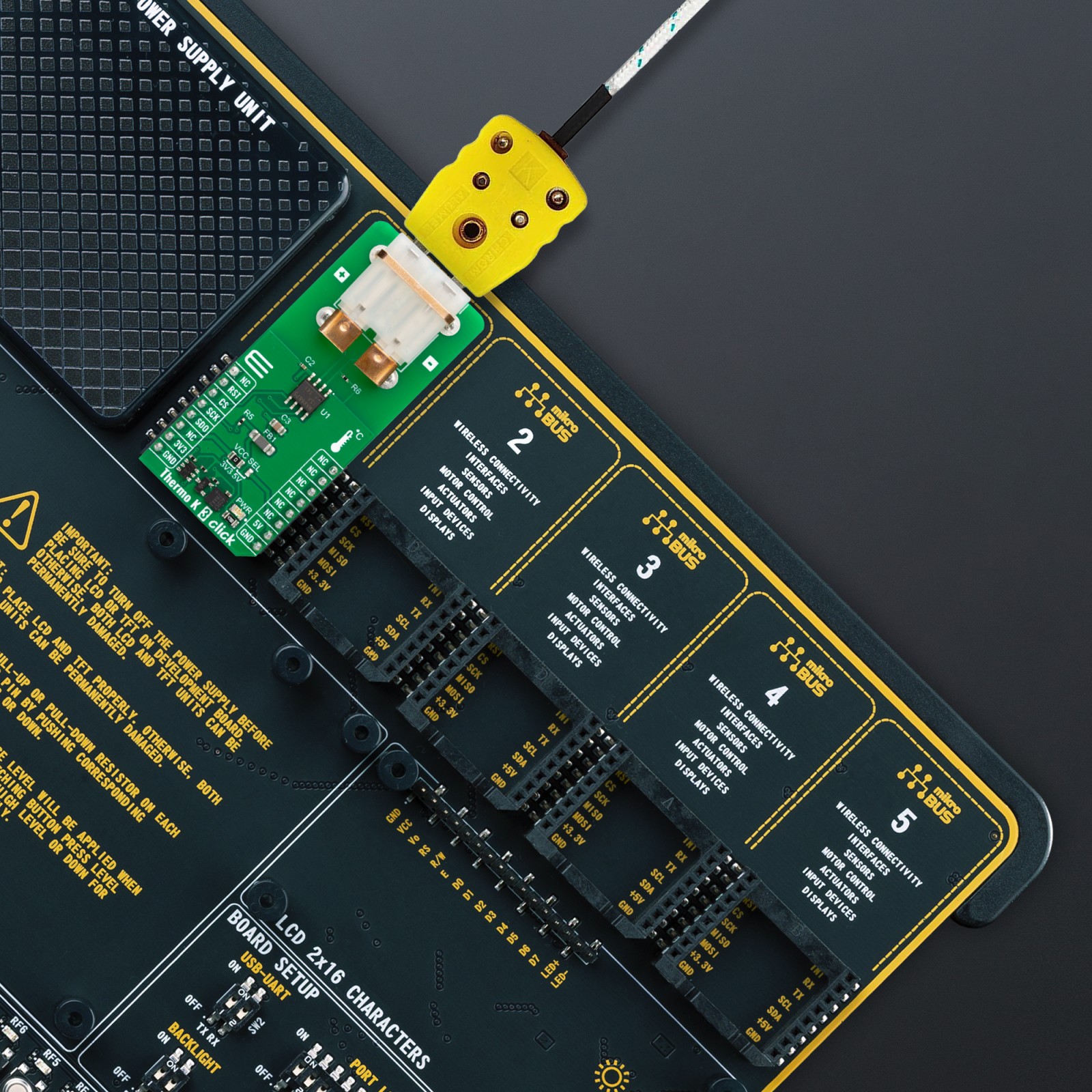
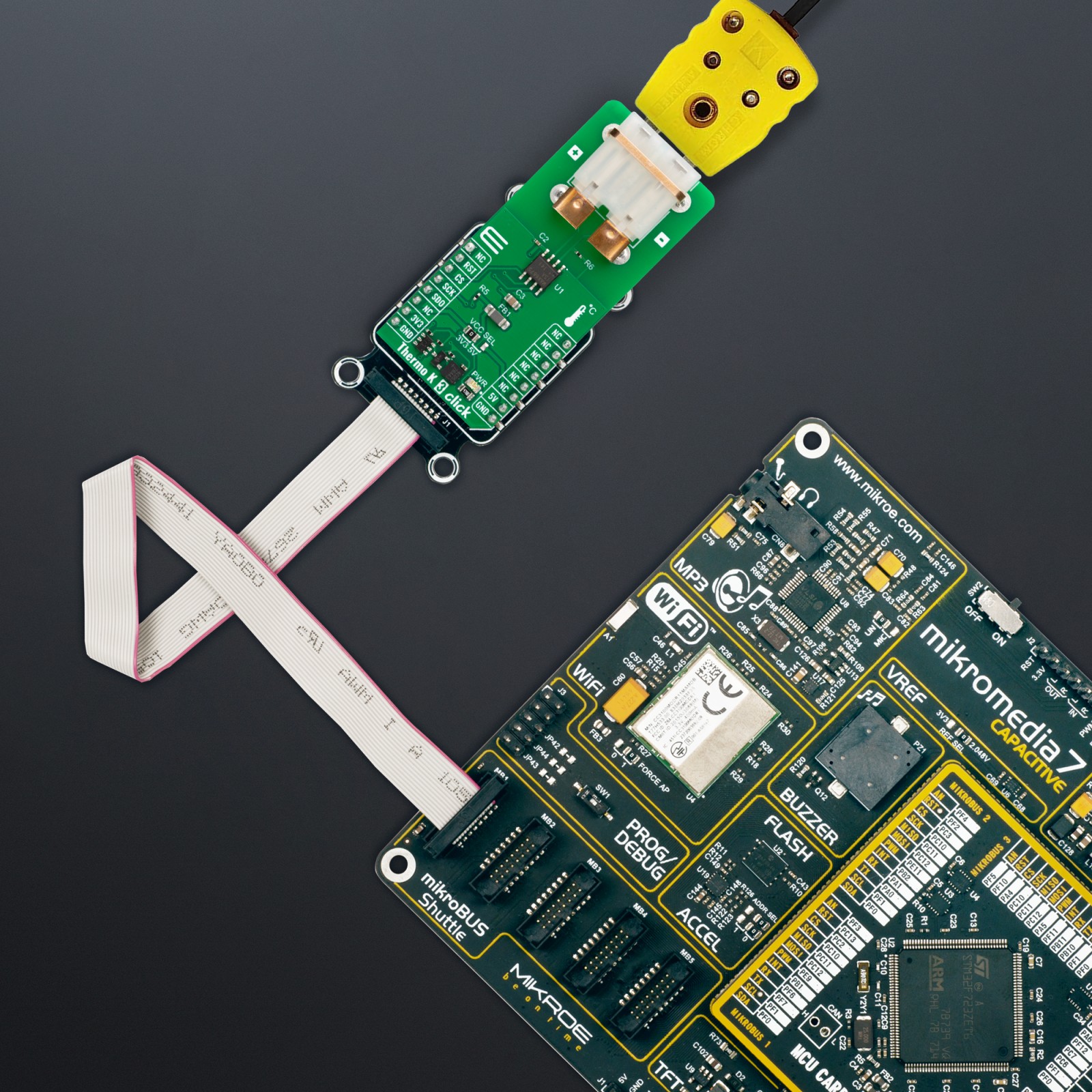
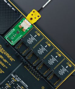
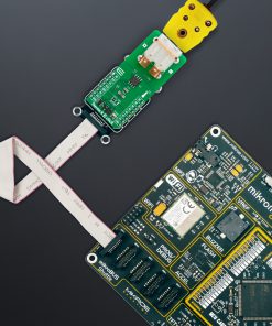
The Thermo K 3 Click uses a 3-Wire (read-only) SPI serial interface to communicate with the host MCU with clock frequency up to 4.3MHz. Besides the temperature, you can get the data of the open thermocouple detection. For this feature, the T- of the PCC-SMP connector is grounded over the R6 0Ω resistor. You can desolder it if you do not need this feature or it does not suit your needs. This Click board™ does not come with the probe itself in the same package; however, a Type-K thermocouple probe with glass braid insulation is available in our store.
This Click board™ can operate with either 3.3V or 5V logic voltage levels selected via the VCC SEL jumper. This way, both 3.3V and 5V capable MCUs can use the communication lines properly. However, the Click board™ comes equipped with a library containing easy-to-use functions and an example code that can be used, as a reference, for further development.
Specifications
Type
Temperature & humidity
Applications
Can be used for the development of hand-held measurement equipment, industrial equipment thermal management, petrochemical thermal management, and more
On-board modules
MAX6675 – cold-junction-compensated K-thermocouple-to-digital converter from Analog Devices
Key Features
Direct digital conversion of Type-K thermocouple output, cold-junction compensation, open thermocouple detection, 12-bit (0.25 °C) resolution, PCC-SMP connector, and more
Interface
SPI
Feature
ClickID
Compatibility
mikroBUS™
Click board size
L (57.15 x 25.4 mm)
Input Voltage
3.3V or 5V
Pinout diagram
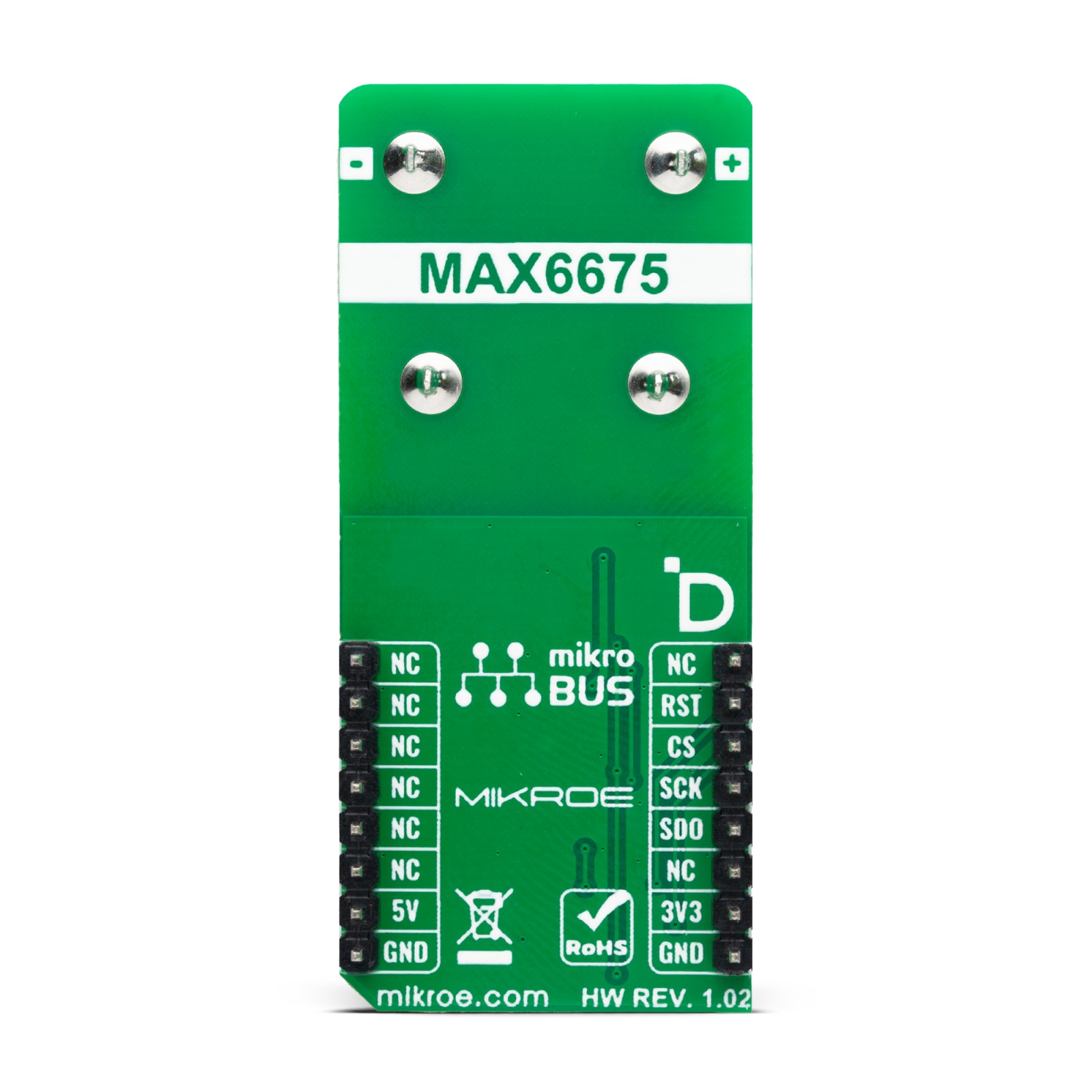
This table shows how the pinout on Thermo K 3 Click corresponds to the pinout on the mikroBUS™ socket (the latter shown in the two middle columns).
Onboard settings and indicators
Label | Name | Default | Description |
---|---|---|---|
LD1 | PWR | – | Power LED Indicator |
JP1 | VCC SEL | Left | Power/Logic Level Voltage Selection 3V3/5V: Left position 3V3, Right position 5V |
Thermo K 3 Click electrical specifications
Description | Min | Typ | Max | Unit |
---|---|---|---|---|
Supply Voltage | 3.3 | – | 5 | V |
Thermocouple Operating Range | 0 | – | 1024 | °C |
TDC Resolution | – | 12 | – | bit |
TDC Resolution | – | 0.25 | – | °C |
Software Support
We provide a library for the Thermo K 3 Click as well as a demo application (example), developed using MIKROE compilers. The demo can run on all the main MIKROE development boards.
Package can be downloaded/installed directly from NECTO Studio Package Manager (recommended), downloaded from our LibStock™ or found on Mikroe github account.
Library Description
This library contains API for Thermo K 3 Click driver.
Key functions
-
thermok3_read_data
This function reads a raw data output by using the SPI serial interface. -
thermok3_read_temperature
This function reads a raw data output and converts it to temperature in Celsius.
Example Description
This example demonstrates the use of Thermo K 3 Click board™ by reading and displaying the temperature measurements.
void application_task ( void )
{
float temperature = 0;
err_t error_flag = thermok3_read_temperature ( &thermok3, &temperature );
if ( THERMOK3_OK == error_flag )
{
log_printf( &logger, " Temperature: %.2f Crnn", temperature );
}
else if ( THERMOK3_OPEN_THERMOCOUPLE == error_flag )
{
log_printf( &logger, " NO thermocouple inputrnn" );
}
Delay_ms ( 1000 );
}
The full application code, and ready to use projects can be installed directly from NECTO Studio Package Manager (recommended), downloaded from our LibStock™ or found on Mikroe github account.
Other Mikroe Libraries used in the example:
- MikroSDK.Board
- MikroSDK.Log
- Click.ThermoK3
Additional notes and informations
Depending on the development board you are using, you may need USB UART click, USB UART 2 Click or RS232 Click to connect to your PC, for development systems with no UART to USB interface available on the board. UART terminal is available in all MIKROE compilers.
mikroSDK
This Click board™ is supported with mikroSDK – MIKROE Software Development Kit. To ensure proper operation of mikroSDK compliant Click board™ demo applications, mikroSDK should be downloaded from the LibStock and installed for the compiler you are using.
For more information about mikroSDK, visit the official page.