Charger 17 Click
R330.00 ex. VAT
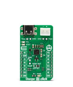
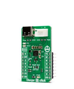
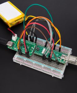
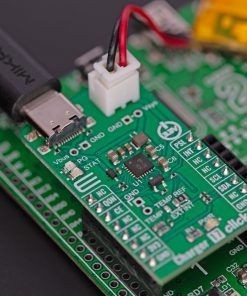
Charger 17 Click is a compact add-on board that provides a single-cell battery charging solution. This board features the RT9471, a 3A single-cell switching battery charger from Richtek. It is a highly-integrated battery charge and system power-path management device for single-cell Li-Ion and Li-Polymer batteries. The high-efficiency 1.5MHz synchronous switch-mode buck charger achieves up to 92% charge efficiency at 2A with 5V input and 3.8V battery. This Click board™ makes the perfect solution for the development of Li-Ion/Polymer battery chargers for portable devices and accessories, power tools, and more.
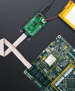
Charger 17 Click is supported by a mikroSDK compliant library, which includes functions that simplify software development. This Click board™ comes as a fully tested product, ready to be used on a system equipped with the mikroBUS™ socket.
Stock: Lead-time applicable.
| 5+ | R313.50 |
| 10+ | R297.00 |
| 15+ | R280.50 |
| 20+ | R269.94 |
How does it work?
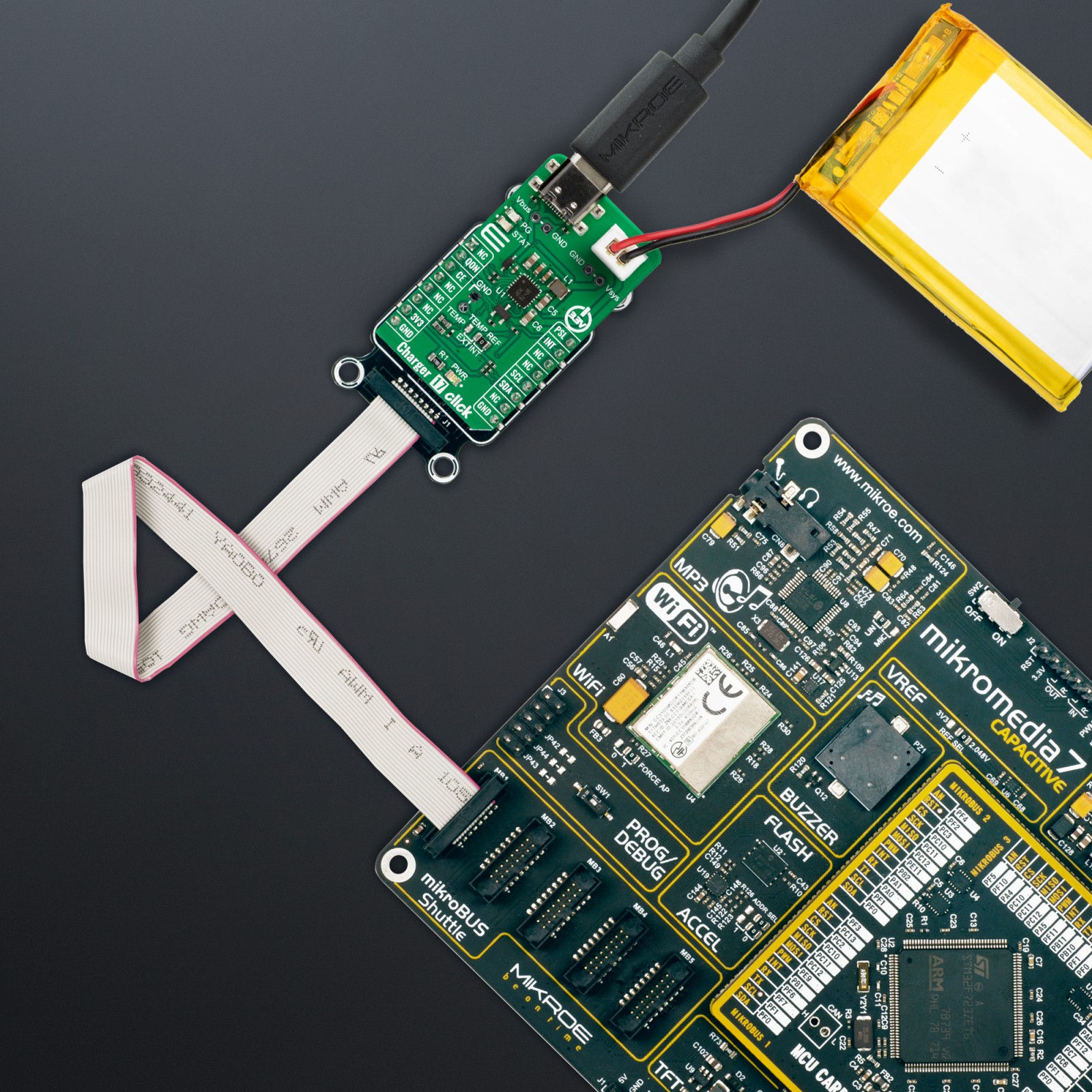
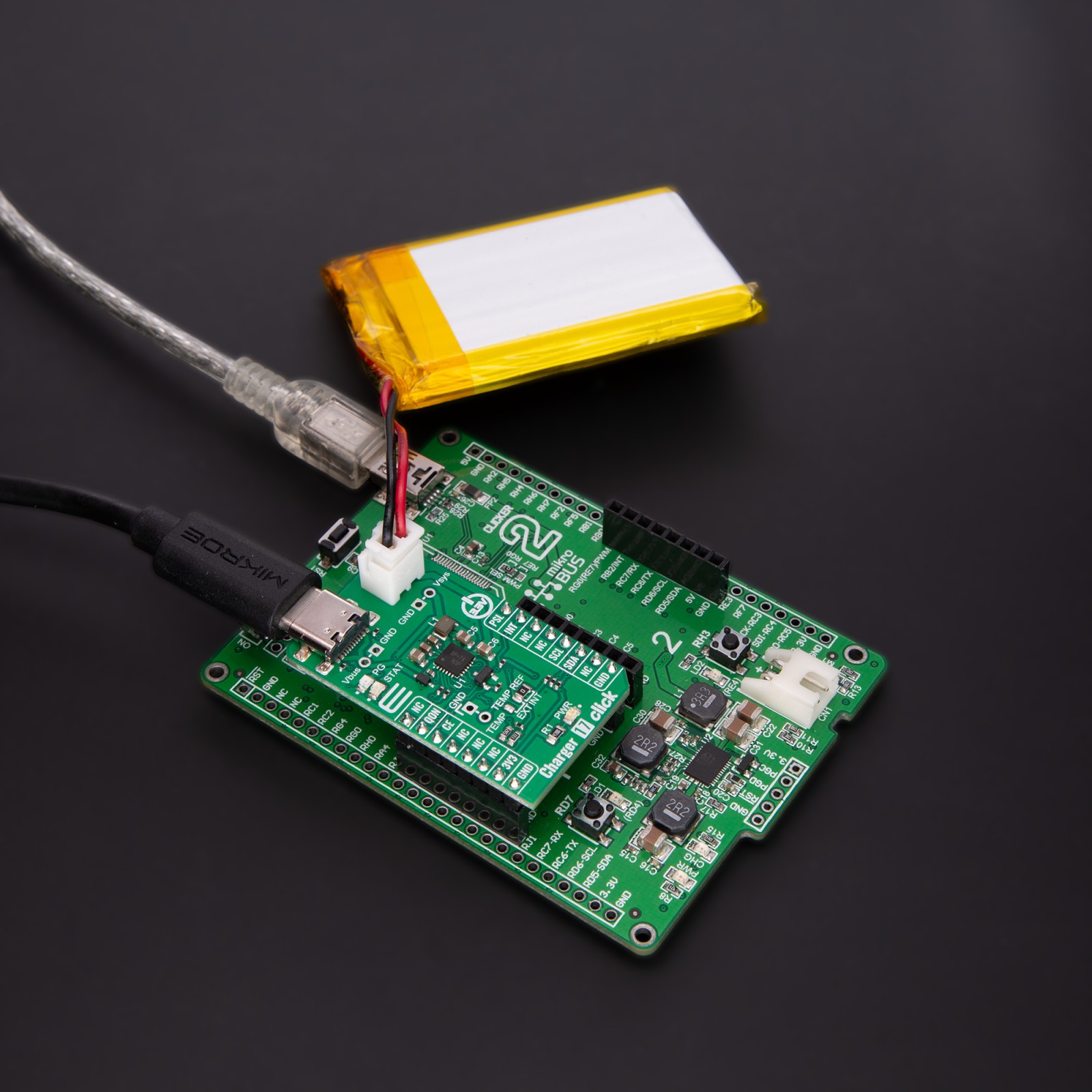
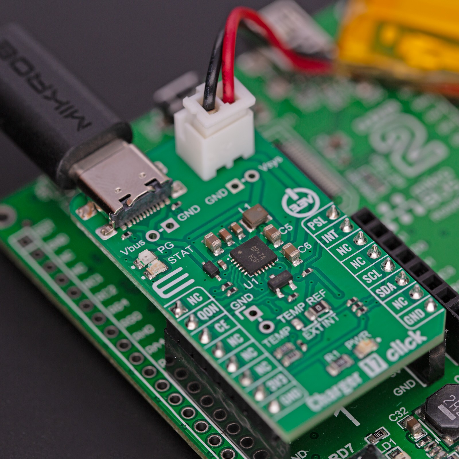
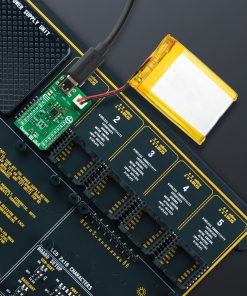
Charger 17 Click is based on the RT9471, a 3A single-cell switching battery charger from Richtek. The RT9471 supports USB OTG current and voltage limit regulations. In addition, the charger supports several protection features, such as over-temperature, VBUS over-voltage, battery over-voltage, system over-voltage, system under-voltage, and more. The Charger 17 Click for power input uses a USB C connector and 5V, where in addition, you can use a VBUS/GND header for powering it from another external source as the VBUS RT4971 input has an operating range from 3.9 up to 13.5V. Charger 17 Click uses a properly labeled JST connector for connecting a battery, and one should take note of the battery polarity as the JST battery connector is NOT standardized. In addition to the battery connector, there is an SYS/GND header as a converter output connection point.
.jpg)
The device provides automatic power path selection to the supply system from the USB C connector, the connected battery, or both of them over the VSYS/GND header. There is a shipping mode that allows you to turn the battery off when shipping or in storage, thus extending the battery life. During charge status, the charger monitors the battery’s voltage and selects the appropriate mode (battery supply mode to charge battery mode). In USB OtG applications, the RT9471 can achieve up to 92% boost efficiency at 1A with a 3.8V battery and a 5.15V output voltage. The RT9471 charger indicates how good the power source is over the power good PG LED indicator. This status includes applied VBUS when not in Sleep mode, charger thermal values under threshold settings when not in HZ mode, and more. The charging status can be visually monitored over the STAT LED indicator.
The RT9471 supports JEITA protection during charge mode. The charger can measure the battery’s temperature over the TEMP/GND header and the additional NTC thermistor. This feature can be selected from the TEMP REF solder jumper, which is set to the internal position by default. In both ways, the temperature window is programmed over the resistor divider. The device will stop charging the battery if the battery’s temperature is lower than T1 or higher than T4 values. For more information, please check the attached datasheet.
Charger 17 Click uses a standard 2-Wire I2C interface to communicate with the host MCU, with speeds up to 3.4Mbits. There are some other functionalities for this Click board™, such as charge enable CE pin where you can turn off battery charging when driving this pin LOW. You can also control the BATFET over the QON pin. That includes exiting the shipping mode and system reset. You can select a power source current limit between 0.5A and 2.4A over the PSL pin. The charger can alert poor source detection, VBUS source type detection, and other events over the INT interrupt pin.
This Click board™ can be operated only with a 3.3V logic voltage level. The board must perform appropriate logic voltage level conversion before using MCUs with different logic levels. However, the Click board™ comes equipped with a library containing functions and an example code that can be used, as a reference, for further development.
Specifications
Type
Battery charger
Applications
Can be used for the development of Li-Ion/Polymer battery chargers for portable devices and accessories, power tools, and more
On-board modules
RT9471 – 3A single-cell switching battery charger from Richtek
Key Features
JST connector for charging single-cell Li-Ion and Li-Polymer batteries, USB C external power supply, or over the VBUS/GND header, high charger efficiency, high boost efficiency, supports USB On-the-Go with current and voltage limit regulation, up to 3150mA of current charging range, over-temperature protection, VBUS over-voltage protection, battery over-voltage protection, and more
Interface
I2C
Feature
No ClickID
Compatibility
mikroBUS™
Click board size
M (42.9 x 25.4 mm)
Input Voltage
3.3V
Pinout diagram
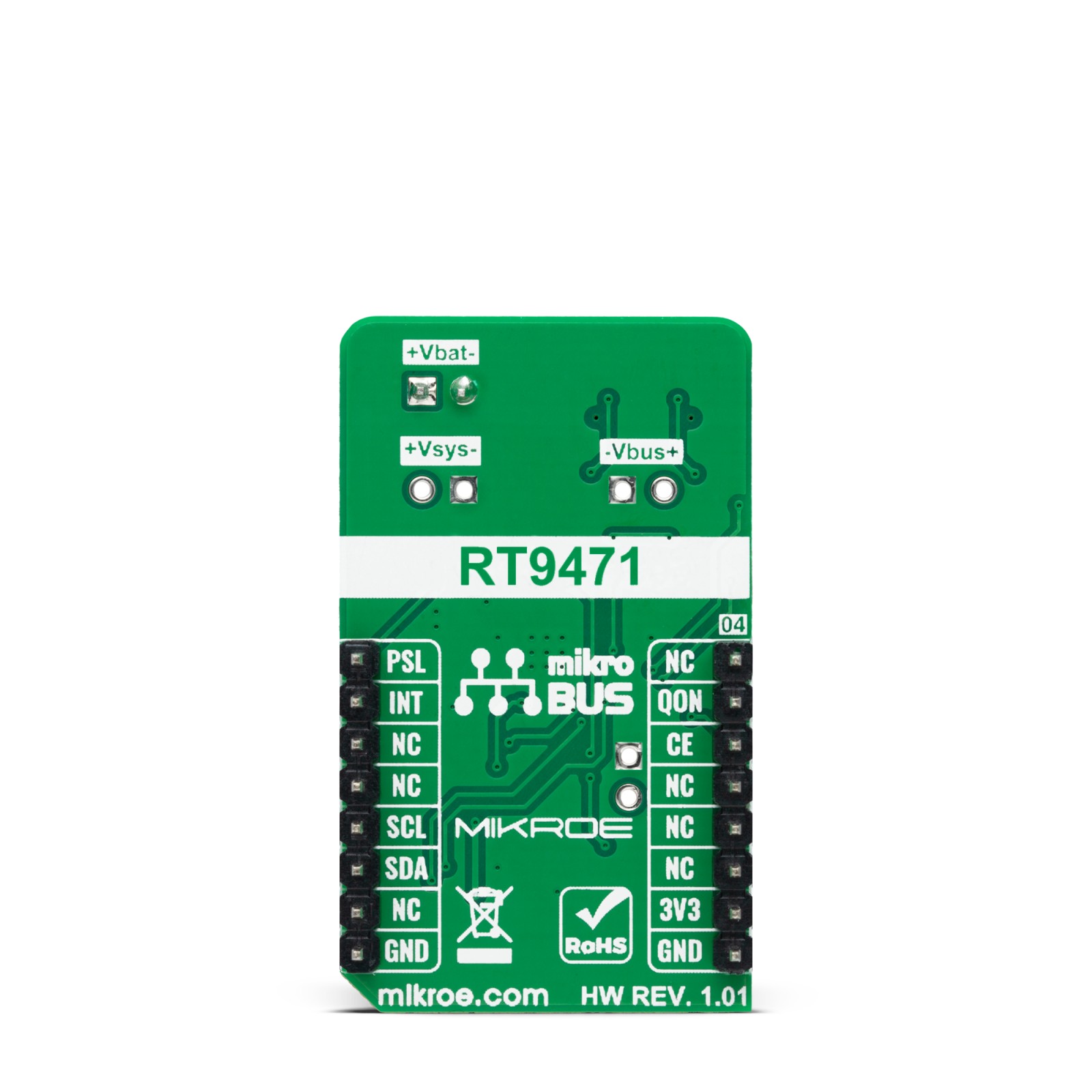
This table shows how the pinout on Charger 17 Click corresponds to the pinout on the mikroBUS™ socket (the latter shown in the two middle columns).
Onboard settings and indicators
| Label | Name | Default | Description |
|---|---|---|---|
| LD1 | PWR | – | Power LED Indicator |
| – | PG | – | Power Good LED Indicator |
| – | STAT | – | Status LED Indicator |
| JP1 | TEMP REF | Right | Temperature Reference Selection EXT/INT: Left position EXT, Right position INT |
Charger 17 Click electrical specifications
| Description | Min | Typ | Max | Unit |
|---|---|---|---|---|
| Supply Voltage | – | 3.3 | – | V |
| VBUS Operating Range | 3.9 | – | 13.5 | V |
| Charge Voltage Range | 3.9 | – | 4.7 | V |
| Charge Current Regulation Range | 0 | – | 3150 | mA |
Software Support
We provide a library for the Charger 17 Click as well as a demo application (example), developed using MikroElektronika compilers. The demo can run on all the main MikroElektronika development boards.
Package can be downloaded/installed directly from NECTO Studio Package Manager (recommended), downloaded from our LibStock™ or found on Mikroe github account.
Library Description
This library contains API for Charger 17 Click driver.
Key functions
-
charger17_enable_chargingThis function enables charging by setting the CE pin to low logic state. -
charger17_set_psel_2400mAThis function sets charging current to 2400mA by setting the PSEL pin to low logic state. -
charger17_read_registerThis function reads data from the selected register by using I2C serial interface.
Example Description
This example demonstrates the use of Charger 17 Click board™ by enabling battery charging and displaying the charging status.
void application_task ( void )
 {
     uint8_t ic_status, status_0;
     if ( CHARGER17_OK == charger17_read_register ( &charger17, CHARGER17_REG_IC_STATUS, &ic_status ) )
     {
         charger17_parse_ic_status ( ic_status );
     }
     if ( CHARGER17_OK == charger17_read_register ( &charger17, CHARGER17_REG_STAT0, &status_0 ) )
     {
         charger17_parse_status_0 ( status_0 );
     }
     Delay_ms ( 1000 );
 }
The full application code, and ready to use projects can be installed directly from NECTO Studio Package Manager (recommended), downloaded from our LibStock™ or found on Mikroe github account.
Other Mikroe Libraries used in the example:
- MikroSDK.Board
- MikroSDK.Log
- Click.Charger17
Additional notes and informations
Depending on the development board you are using, you may need USB UART click, USB UART 2 Click or RS232 Click to connect to your PC, for development systems with no UART to USB interface available on the board. UART terminal is available in all MikroElektronika compilers.
mikroSDK
This Click board™ is supported with mikroSDK – MikroElektronika Software Development Kit. To ensure proper operation of mikroSDK compliant Click board™ demo applications, mikroSDK should be downloaded from the LibStock and installed for the compiler you are using.
For more information about mikroSDK, visit the official page.
Resources
Downloads
| Weight | 18 g |
|---|---|
| Brand | MikroElektronika |


