How does it work?
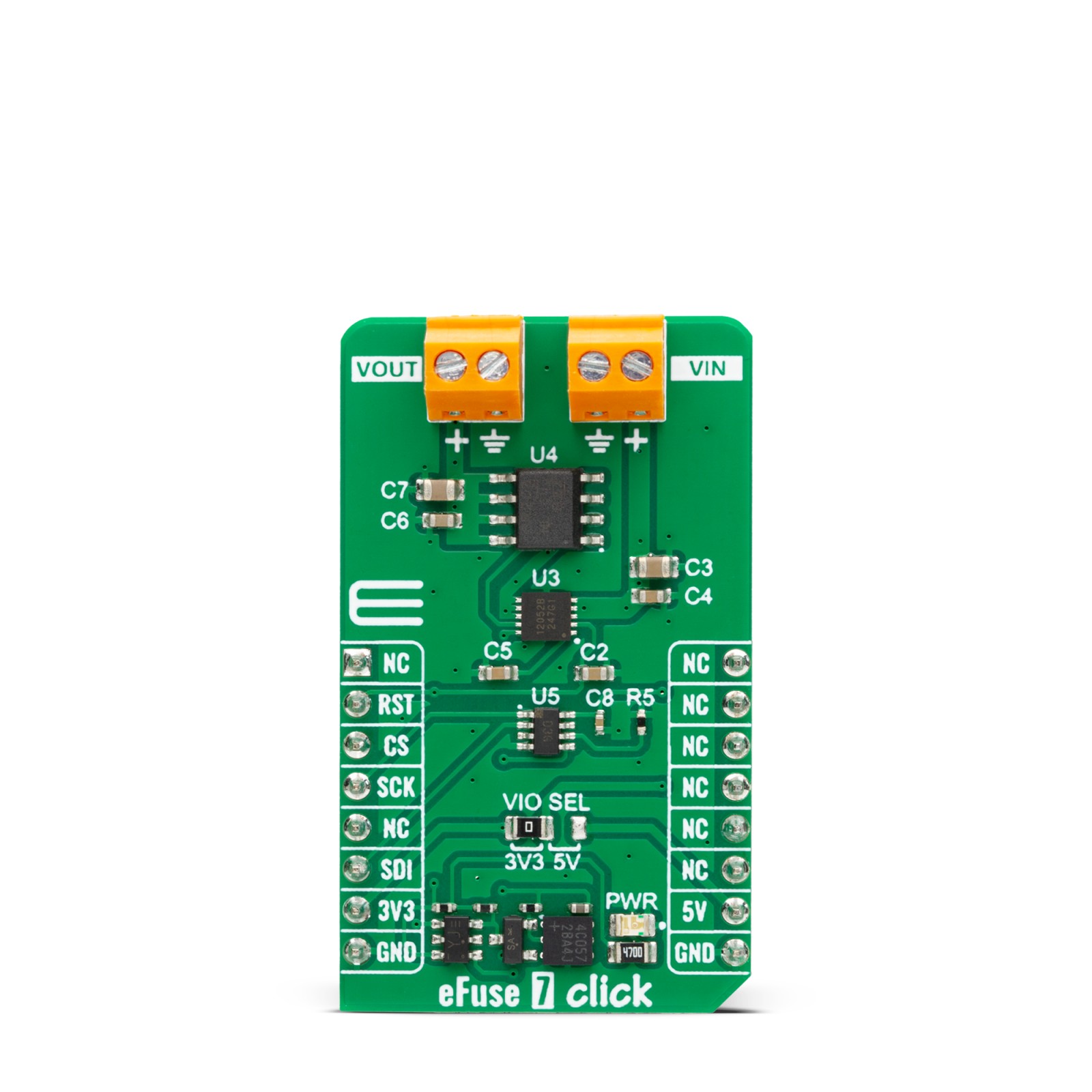
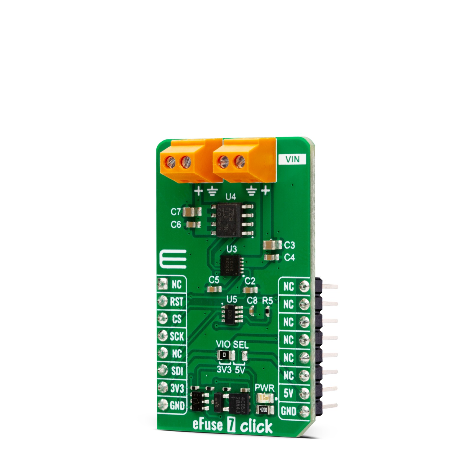
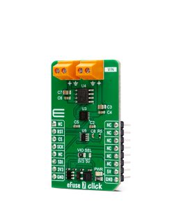
eFuse 7 Click is based on the LS12052BD33, an eFuse with over-voltage protection and blocking FET control from Littelfuse. It is a current limit load switch with an integrated power load switch designed to manage current/voltage/start-up voltage ramp to the connected load. The internal MOSFET of the device will start conducting and allowing current to flow from IN to OUT as VIN rises by enabling the eFuse with an accurate ON/OFF threshold of 1.29V and 1.19V, respectively. After a Start-Up sequence, the eFuse will actively monitor its load current and input voltage. The eFuse will ensure that any harmful spikes are safely clamped to a pre-determined level at the output. The eFuse will shut down its internal MOSFET if the overload of the current limit is exceeded or the device’s temperature exceeds its threshold.
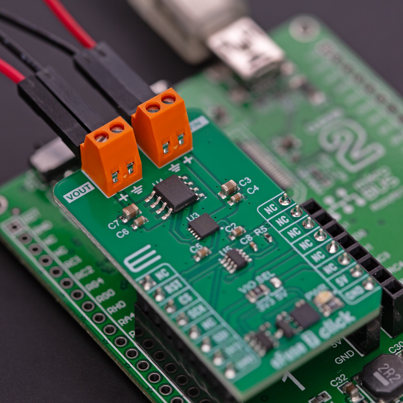
The eFuse uses the TP86R203NL, an N-channel MOS from Toshiba, as a gate to the output screw terminal. The current limit on this eFuse 7 Click can be programmed. For this purpose, there is the AD5227, a 64-position up/down control digital potentiometer from Analog Devices. This 10K end-to-end potentiometer, in variable resistor configuration, is used to feed the current limit program pin of the eFuse.
eFuse 7 Click uses a simple 3-Wire serial interface of the digital potentiometer to allow the host MCU to set the current limit to this Click board™. Over the RST pin, you can enable the eFuse with the logic HIGH.
This Click board™ can operate with either 3.3V or 5V logic voltage levels selected via the VIO SEL jumper. This way, both 3.3V and 5V capable MCUs can use the communication lines properly. However, the Click board™ comes equipped with a library containing easy-to-use functions and an example code that can be used, as a reference, for further development.
Specifications
Type
Power Switch
Applications
Can be used for the development of robust protection for multiple faults on the system rail and current limiting for systems such as telecom radios and industrial printers
On-board modules
LS12052BD33 – eFuse with over-voltage protection and blocking FET control from Littelfuse
Key Features
Wide operating voltage, adjusting current limit, short-circuit protection features, thermal shutdown protection, and auto recovery, reverse current blocking and more
Interface
GPIO
Feature
ClickID
Compatibility
mikroBUS™
Click board size
M (42.9 x 25.4 mm)
Input Voltage
3.3V or 5V
Pinout diagram
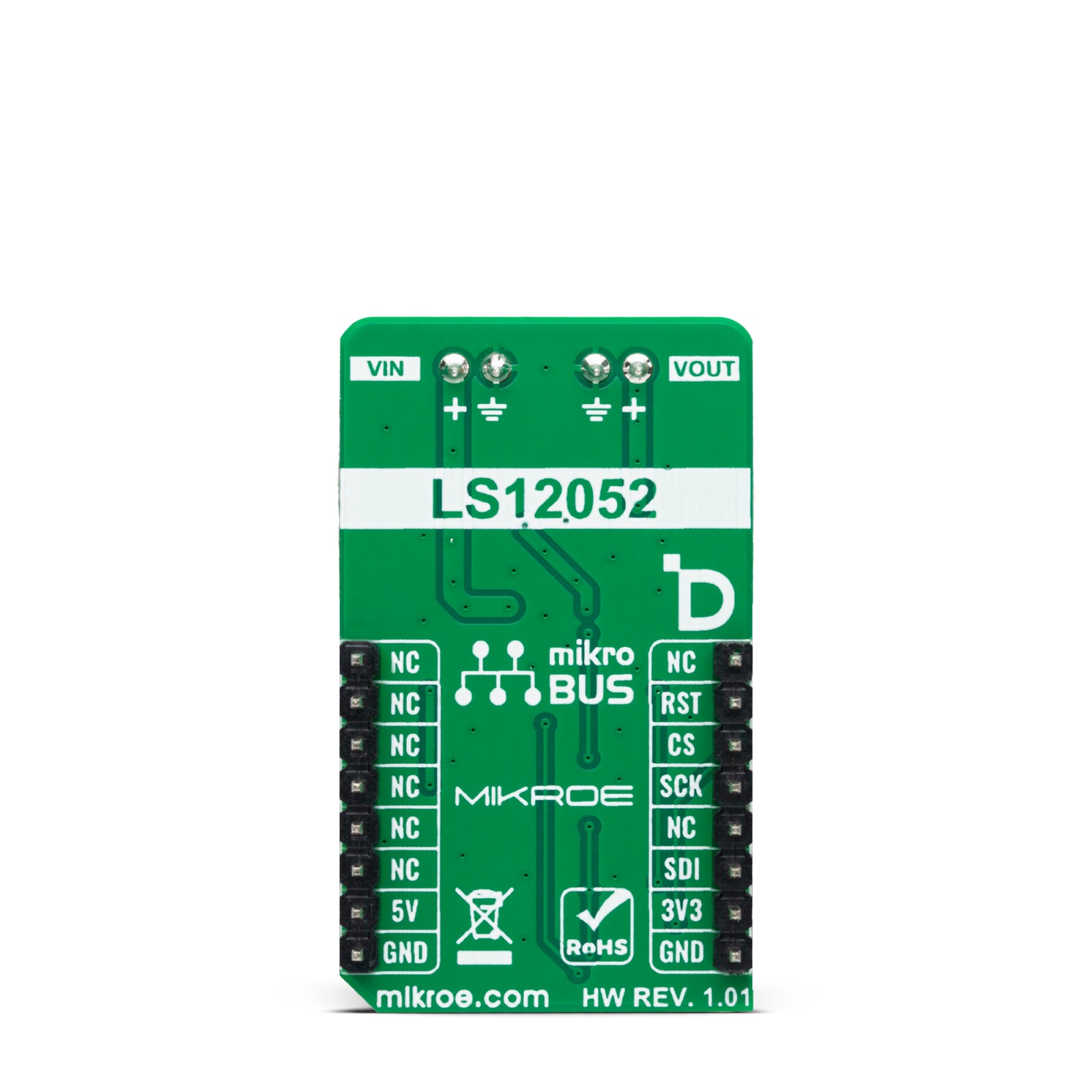
This table shows how the pinout on eFuse 7 Click corresponds to the pinout on the mikroBUS™ socket (the latter shown in the two middle columns).
Onboard settings and indicators
Label | Name | Default | Description |
---|---|---|---|
LD1 | PWR | – | Power LED Indicator |
JP1 | VIO SEL | Left | Logic Level Voltage Selection 3V3/5V: Left position 3V3, Right position 5V |
eFuse 7 Click electrical specifications
Description | Min | Typ | Max | Unit |
---|---|---|---|---|
Supply Voltage | 3.3 | – | 5 | V |
External Power Supply | 2.7 | – | 18 | V |
Current-Limit Program Range | 1 | – | 5 | A |
Software Support
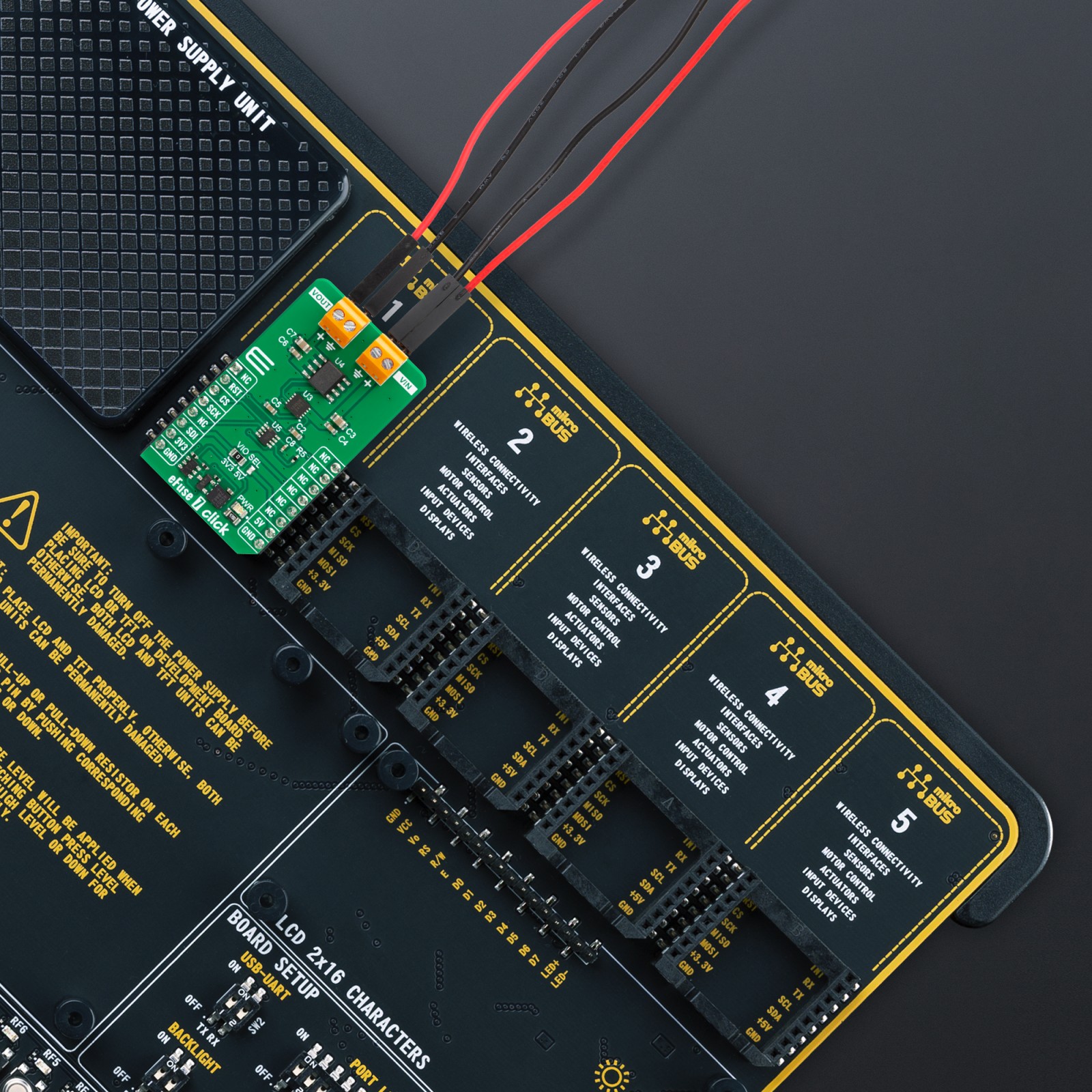
We provide a library for the eFuse 7 Click as well as a demo application (example), developed using MIKROE compilers. The demo can run on all the main MIKROE development boards.
Package can be downloaded/installed directly from NECTO Studio Package Manager (recommended), downloaded from our LibStock™ or found on Mikroe github account.
Library Description
This library contains API for eFuse 7 Click driver.
Key functions
-
efuse7_enable_output
eFuse 7 output enable function. -
efuse7_wiper_inc
eFuse 7 wiper position increase function. -
efuse7_set_limit
eFuse 7 set current limit function.
Example Description
This library contains API for the eFuse 7 Click driver. This driver provides the functions to set the current limiting conditions in order to provide the threshold of the fault conditions.
void application_task ( void )
{
static char index;
if ( 1 == log_read( &logger, &index, 1 ) )
{
if ( ( index >= '0' ) && ( index <= '7' ) )
{
efuse7_set_limit ( &efuse7, limit_value_op[ index - 48 ] );
log_printf( &logger, " >>> Selected mode %c rn", index );
log_printf( &logger, "---------------------------rn" );
Delay_ms( 100 );
}
else
{
log_printf( &logger, " Data not in range! rn" );
log_printf( &logger, "---------------------------rn" );
display_selection( );
Delay_ms( 100 );
}
}
}
The full application code, and ready to use projects can be installed directly from NECTO Studio Package Manager (recommended), downloaded from our LibStock™ or found on Mikroe github account.
Other Mikroe Libraries used in the example:
- MikroSDK.Board
- MikroSDK.Log
- Click.eFuse7
Additional notes and informations
Depending on the development board you are using, you may need USB UART click, USB UART 2 Click or RS232 Click to connect to your PC, for development systems with no UART to USB interface available on the board. UART terminal is available in all MIKROE compilers.
mikroSDK
This Click board™ is supported with mikroSDK – MIKROE Software Development Kit. To ensure proper operation of mikroSDK compliant Click board™ demo applications, mikroSDK should be downloaded from the LibStock and installed for the compiler you are using.
For more information about mikroSDK, visit the official page.