How does it work?
USB MUX Click is based on the TS3USB30E, a USB 2.0 1:2 multiplexer/demultiplexer switch with a single enable from Texas Instruments. It is an ESD-protected device capable of bidirectional switching of high-speed USB 2.0 signals while offering little or no attenuation of the high-speed signals at the outputs. Besides the ESD protection, the TS3USB30E offers a low bit-to-bit skew and high channel-to-channel noise isolation. Also, besides USB 2.0, it is compatible with USB 1.1 standard. The maximum speed the TS3USB30E is capable of is 480Mbps at USB 2.0.
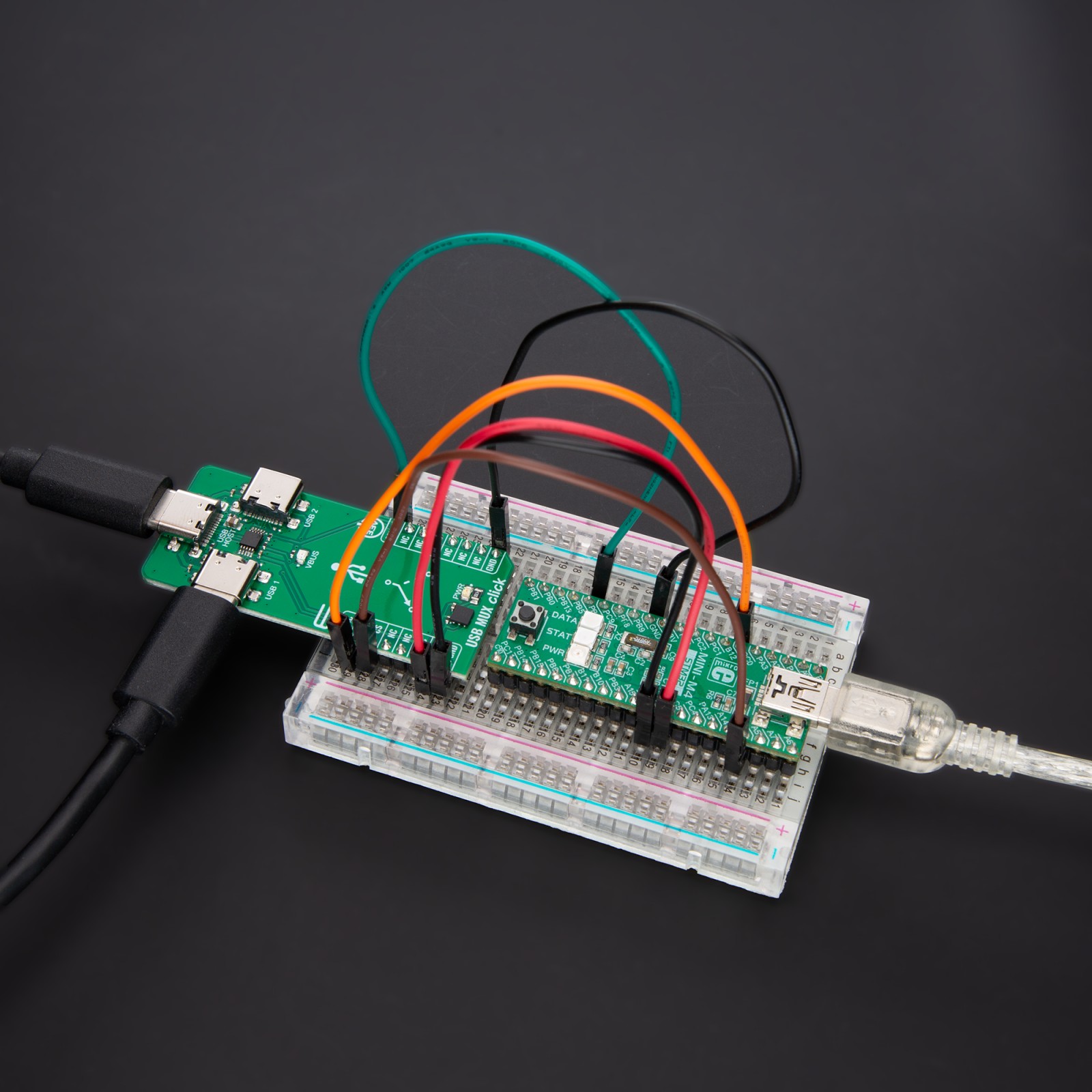
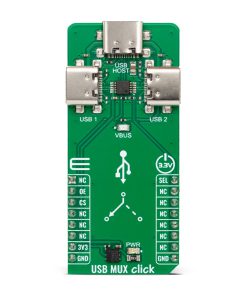
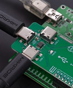
USB MUX Click communicates with the host MCU using a few GPIOs. The OE bus-switch enable pin allows users to isolate the bus when not in use and consume less current. With a LOW logic level set on the OE pin, you can use it in combination with the SEL pin to select one of two USB signal paths and connect it to a common USB signal path, with a LOW logic level to a USB1 and a HIGH logic level to a USB2. The USB1 is set by default over the pull-down resistors R5 and R6, which puts both OE and SEL lines in a low logic state. In addition, the VBUS LED will indicate if the powered USB device is connected to the USB MUX Click.
This Click board™ can only be operated with a 3.3V logic voltage level. The board must perform appropriate logic voltage level conversion before using MCUs with different logic levels. However, the Click board™ comes equipped with a library containing functions and an example code that can be used, as a reference, for further development.
Specifications
Type
USB
Applications
Can be used for the development of multi-purpose signal-switching devices, portable electronics, and other applications with limited USB I/Os
On-board modules
TS3USB30E – USB 2.0 multiplexer/demultiplexer switch from Texas Instruments
Key Features
High bandwidth 1:2 switch, wide bandwidth, support USB 1.1 and high-speed USB 2.0 standards, ESD-protected, single enable, low power consumption, supports partial power-down mode, one host – two outputs, two different hosts- one output, and more
Interface
GPIO
Feature
ClickID
Compatibility
mikroBUS™
Click board size
L (57.15 x 25.4 mm)
Input Voltage
3.3V
Pinout diagram
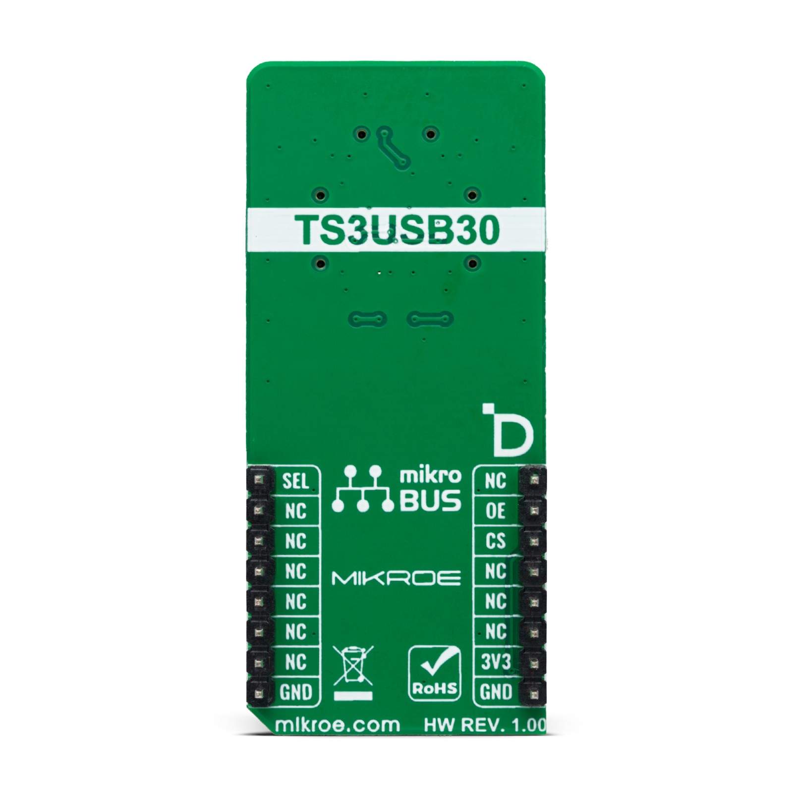
This table shows how the pinout on USB MUX Click corresponds to the pinout on the mikroBUS™ socket (the latter shown in the two middle columns).
Onboard settings and indicators
Label | Name | Default | Description |
---|---|---|---|
LD1 | PWR | – | Power LED Indicator |
LD2 | VBUS | – | Connected USB Device LED Inidcator |
USB MUX Click electrical specifications
Description | Min | Typ | Max | Unit |
---|---|---|---|---|
Supply Voltage | – | 3.3 | – | V |
USB 2.0 Speed | – | – | 480 | Mbps |
ESD Protection (HBM) | – | 8 | – | kV |
Software Support
We provide a library for the USB MUX Click as well as a demo application (example), developed using MIKROE compilers. The demo can run on all the main MIKROE development boards.
Package can be downloaded/installed directly from NECTO Studio Package Manager (recommended), downloaded from our LibStock™ or found on Mikroe github account.
Library Description
This library contains API for USB MUX Click driver.
Key functions
-
usbmux_set_oe_pin
USB MUX set OE pin output function. -
usbmux_enable_output
USB MUX enable output function. -
usbmux_set_output
USB MUX select output function.
Example Description
This example demonstrates the use of the USB MUX Click board. This driver provides functions for device configurations
and for the selection of the output.
void application_task ( void )
{
static char index;
if ( 1 == log_read( &logger, &index, 1 ) )
{
switch ( index )
{
case ( '0' ):
{
log_printf( &logger, " Turning output off. rn" );
usbmux_disable_output( &usbmux );
break;
}
case ( '1' ):
{
log_printf( &logger, " USB1 Enabled and selected. rn" );
usbmux_set_output( &usbmux, USBMUX_USB1_SELECT );
usbmux_enable_output( &usbmux );
break;
}
case ( '2' ):
{
log_printf( &logger, " USB2 Enabled and selected. rn" );
usbmux_set_output( &usbmux, USBMUX_USB2_SELECT );
usbmux_enable_output( &usbmux );
break;
}
default:
{
display_selection( );
}
}
}
}
The full application code, and ready to use projects can be installed directly from NECTO Studio Package Manager (recommended), downloaded from our LibStock™ or found on Mikroe github account.
Other Mikroe Libraries used in the example:
- MikroSDK.Board
- MikroSDK.Log
- Click.USBMUX
Additional notes and informations
Depending on the development board you are using, you may need USB UART click, USB UART 2 Click or RS232 Click to connect to your PC, for development systems with no UART to USB interface available on the board. UART terminal is available in all MIKROE compilers.
mikroSDK
This Click board™ is supported with mikroSDK – MIKROE Software Development Kit. To ensure proper operation of mikroSDK compliant Click board™ demo applications, mikroSDK should be downloaded from the LibStock and installed for the compiler you are using.
For more information about mikroSDK, visit the official page.