N-PLC Click Bundle – AC plug EU
R2,000.00 ex. VAT
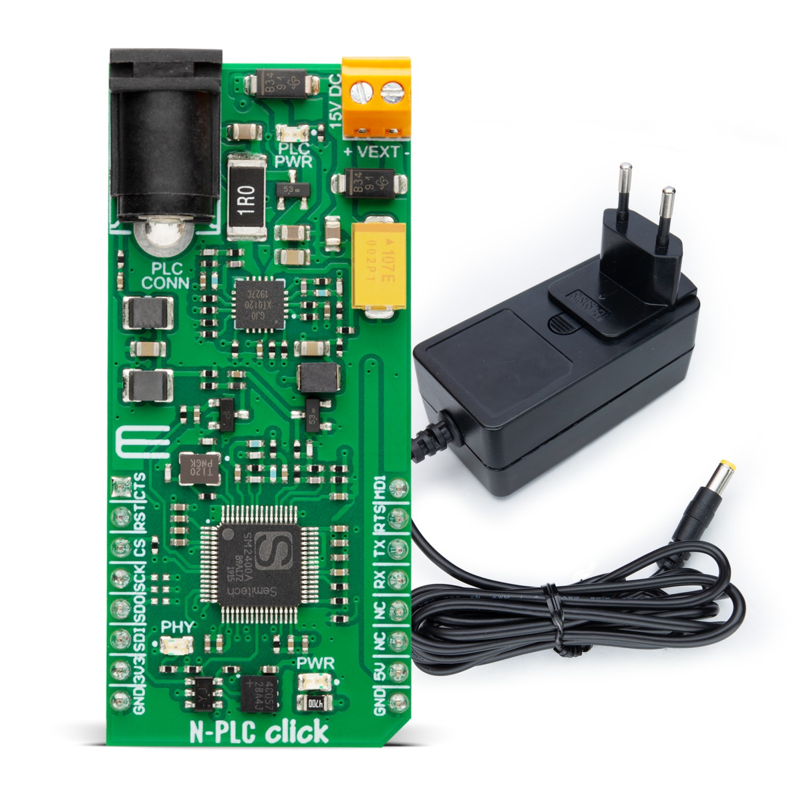
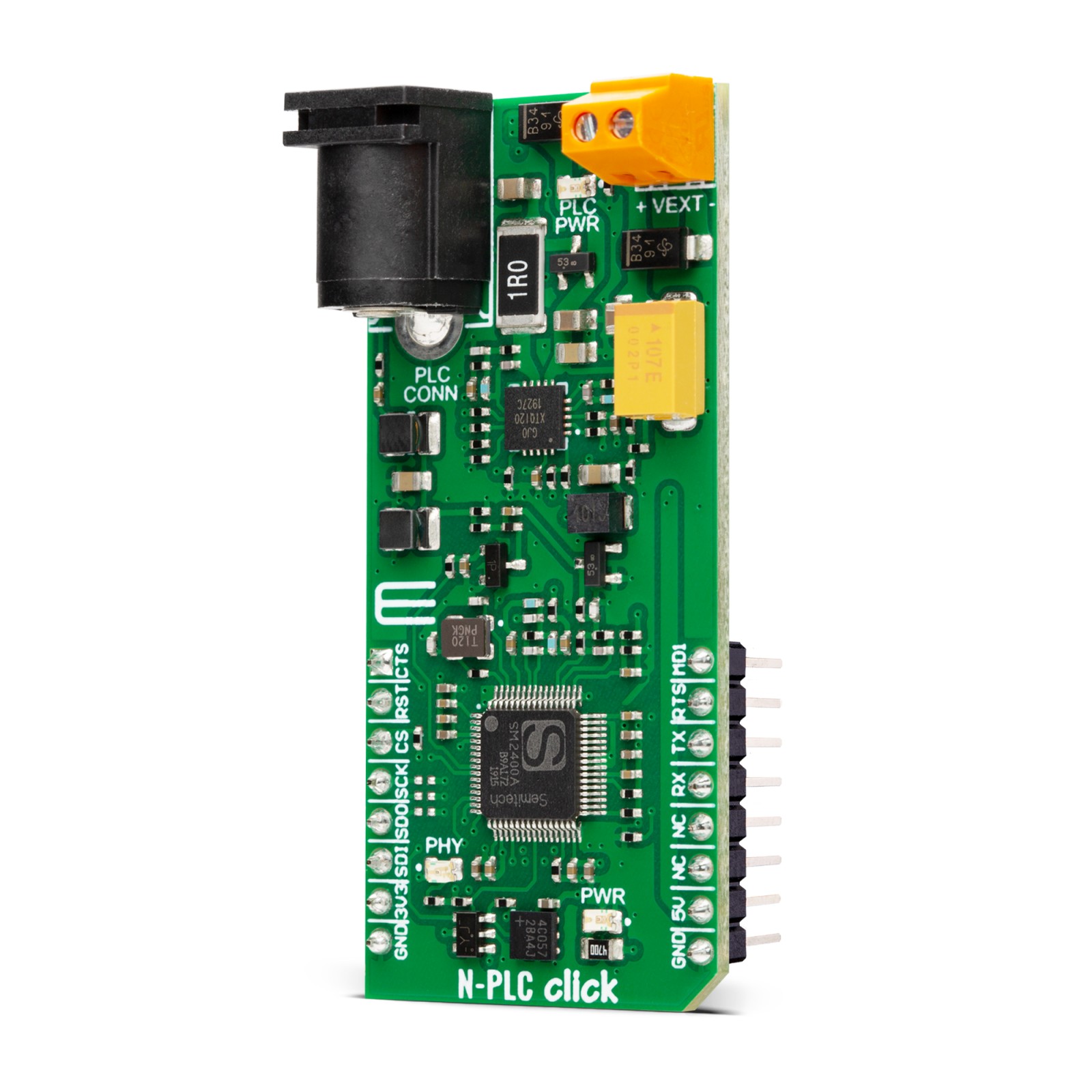
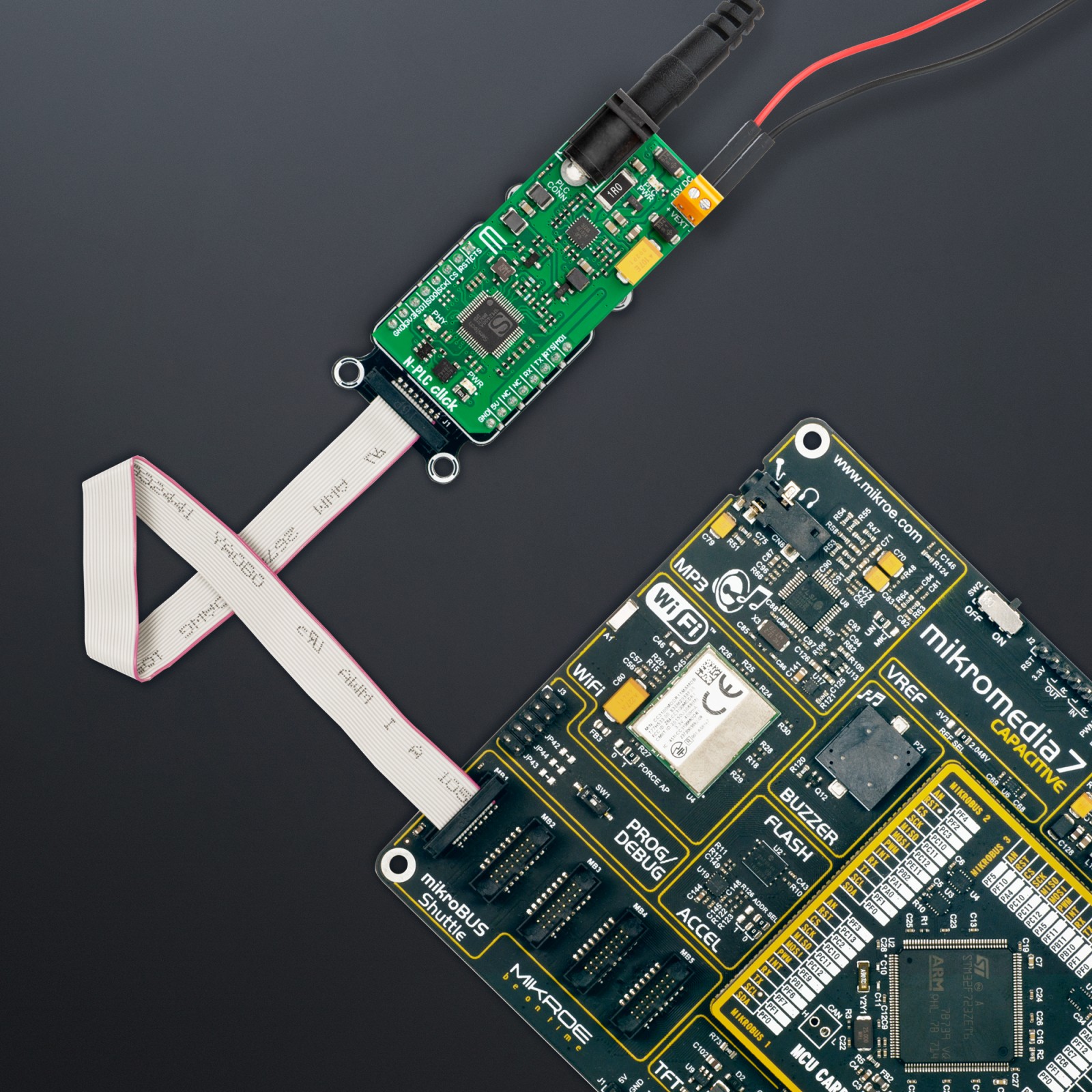
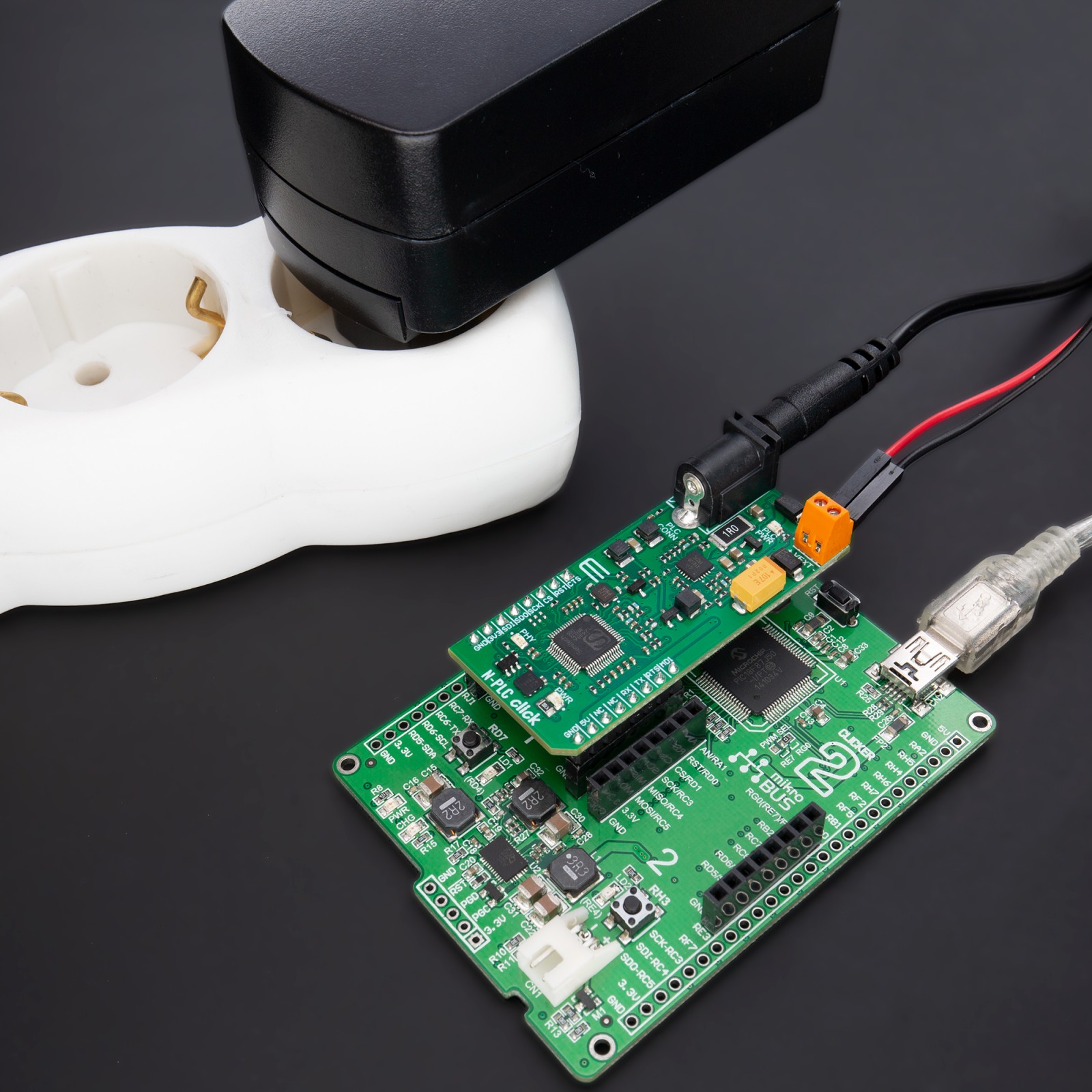
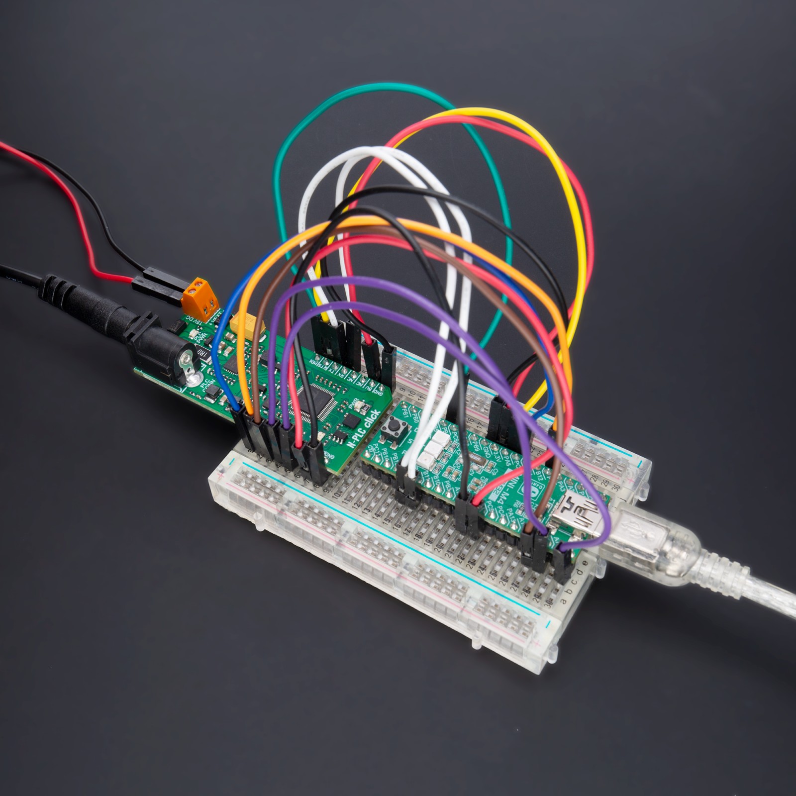
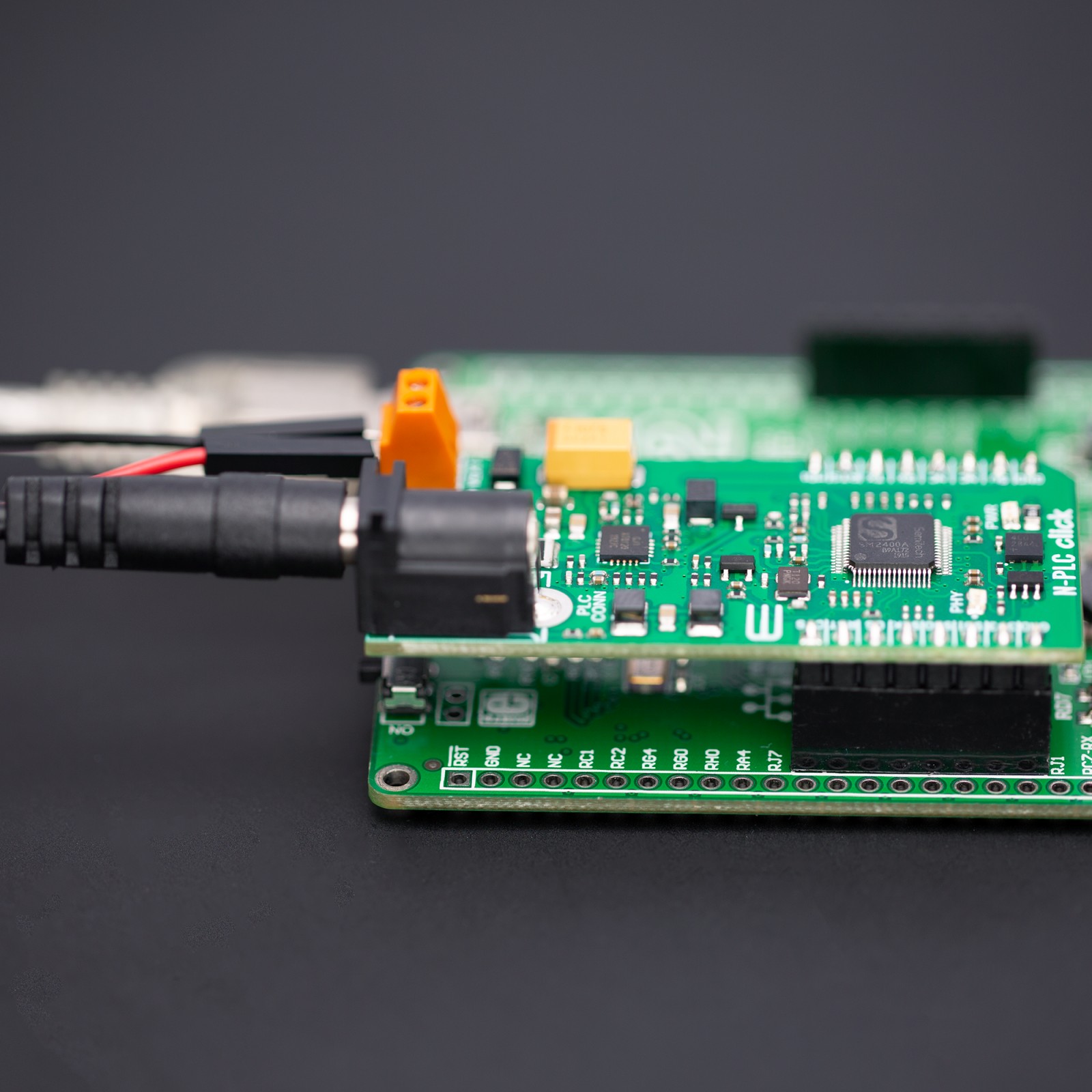
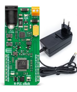
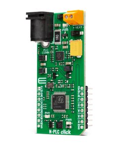
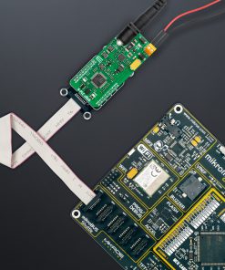
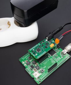
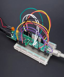
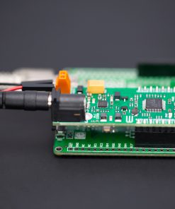
This bundle provides a narrow-band power line communication (N-PLC) solution that uses existing electrical power lines to transmit data signals. It allows users to easily combine the N-PLC Click based on the ultimate N-PLC transceiver, the SM2400, from Semitech with N-PLC Wall Adapter (power line communication AC coupling circuit) to deliver a flexible and elegant solution for home automation and control.
Combining this board with the N-PLC Wall Adapter (110/220VAC) allows testing PLC communication performance over an AC main network. This adapter is also compatible with a wide range of AC plugs from our offer, which makes this bundle suitable for use in different parts of the world.
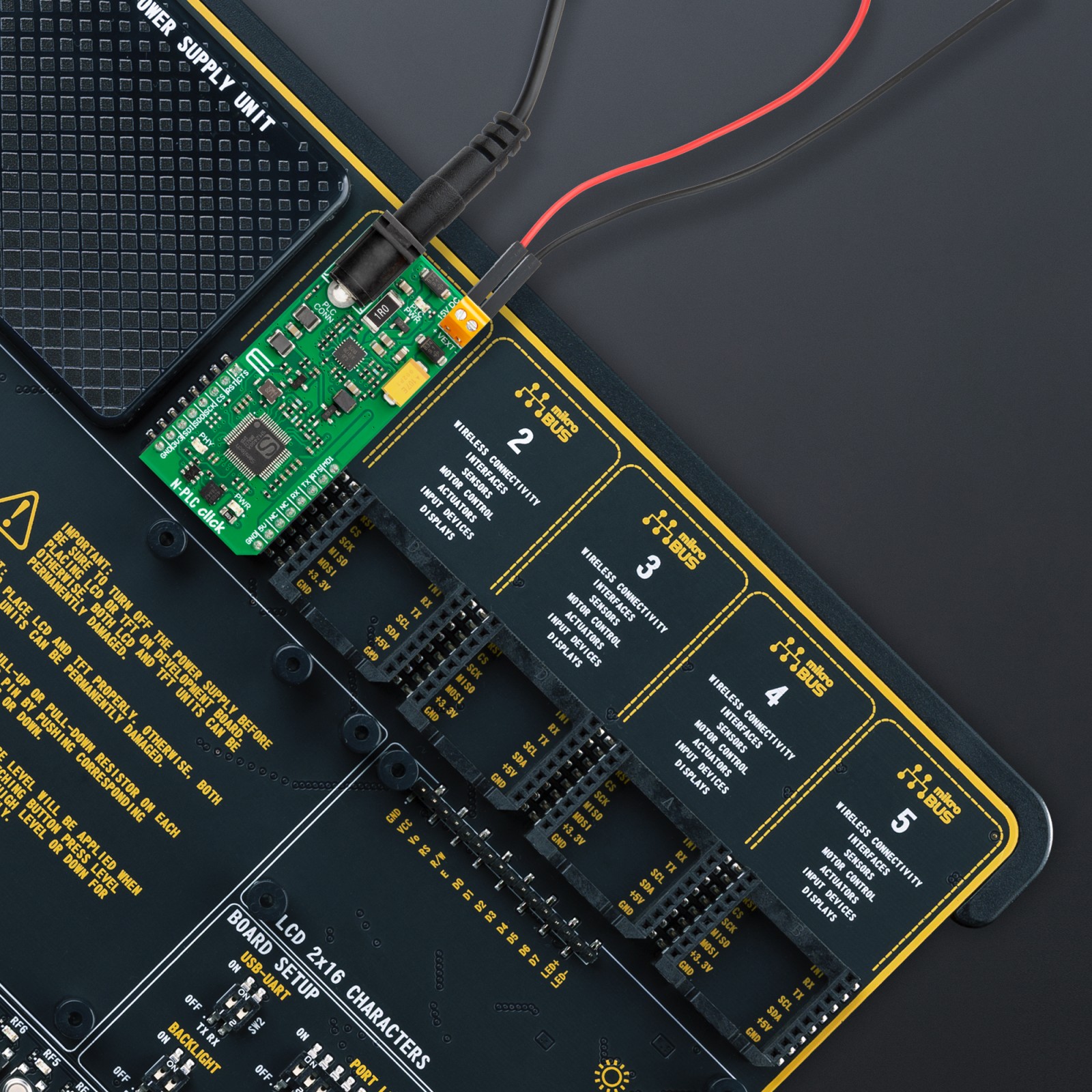
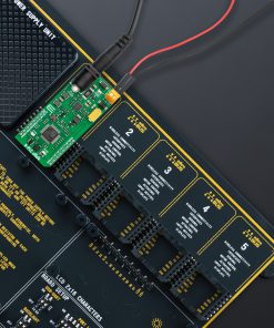
N-PLC Click is fully compatible with the mikroBUS™ socket and can be used on any host system supporting the mikroBUS™ standard. It comes with the mikroSDK open-source libraries, offering unparalleled flexibility for evaluation and customization. What sets this Click board™ apart is the groundbreaking ClickID feature, enabling your host system to seamlessly and automatically detect and identify this add-on board.
The bundle consists of:
- N-PLC Click
- N-PLC Wall Adapter
Stock: Lead-time applicable.
| 5+ | R1,900.00 |
| 10+ | R1,800.00 |
| 15+ | R1,700.00 |
| 20+ | R1,636.00 |
NOTE: This solution must be used by expert technicians only! Due to the high voltage (110/220VAC) present on the non-isolated parts, special care must be taken to avoid electric risks to people’s safety.
How does it work?
N-PLC Click is based on the SM2400, the ultimate Narrow-band Power Line Communication (N-PLC) modem from Semitech that combines cost-effective design optimized for PLC applications with a high level of programmability to address a multitude of communications schemes and evolving standards. The SM2400 system-on-chip (SoC) features a dual-core architecture for dedicated PHY signal processing and MAC layer functionality to guarantee superior communication performance while maintaining high flexibility and programmability for OFDM-based and other open standards and fully customized implementations. It has a set of firmware options implementing IEEE 1901.2 compliant PHY and MAC layers, a 6LoWPAN data link layer, PRIME, G3-PLC, and other special modes tailored for industrial IoT applications.
.jpg)
The SM2400 combines the benefits of programmable architecture with power and efficiency by utilizing a DSP core configured specifically for N-PLC modulations and a dedicated 32-bit core that runs protocols. It contains a high-speed 256-bit AES-CCM engine to ensure standard compliance and secure communication, and all the necessary mixed-signal components, such as ADC, DAC, gain control and two OpAmp to deliver a cost-effective N-PLC system design for any application.
In addition to the SM2400, this Click board™ also includes a PLC line driver, the SGM8423, a high efficiency, Class A/B, low distortion power line driver. It is optimized to accept a signal from a Power Line Carrier modem, for example, one like the SM2400, which is presented in the example code, where two such boards talk to each other in a transmitter/receiver configuration. Besides directly performing enable/shutdown control of the line driver, the SM2400 has one diagnostic signal that can indicate error conditions, such as overcurrent or overheating, reported by the line driver. In addition, it is also possible to supply high voltage (110/220VAC) as an input on the PLC CONN connector, which will be converted into a signal of the appropriate level via the N-PLC Wall Adapter, a simple yet very useful power line communication AC coupling circuit for safe and secure operation. The green PLC PWR LED signal that the N-PLC Wall Adapter is connected and powered.
The SM2400 communicates with an MCU using the UART interface, as its main one, with commonly used UART RX and TX pins and the optional hardware flow control pins UART CTS and RTS (Clear to Send and Ready to Send). The UART interface serves as the primary interface to a host, which can be an MCU or a converter, such as serial-to-USB. As an alternative to the UART interface, users also have at their disposal the lines of the SPI serial interface (to use this interface, it is necessary to populate the appropriate 0Ω resistors to activate the SPI lines).
The SM2400 executes its firmware from internal memory, with the loaded code at a boot time. The SM2400 can boot either from an external SPI flash, the AT25FF041A, or from a host MCU via UART interface depending on the logic state of the MD1 pin of the mikroBUS™ socket (1 – boot over UART interface that allows direct firmware download (boot from the host), 0 – boot from external SPI flash memory), with the host MCU being the Master. In addition, the SM2400 provides the possibility of a reset via the RST pin of the mikroBUS™ socket (asserting this pin causes full chip reset and reboot), as well as visual detection of the communication status via the red PHY LED, which is asserted when an incoming packet is detected.
The power supply of this Click board™ is performed very simply, without any additional hardware configuration (depending on the power supply capability and the desired range). It is possible to power the board in two ways: internally and externally. By default, the board power will be provided internally over the LM5158 boost converter in the value of 15V, which is obtained from the 5V mikroBUS™ power rail. When applying an external power supply of 15VDC on the VEXT terminal, the N-PLC Click will automatically be powered from the external source thanks to the protection of the converter, which automatically recognizes the presence of the external power supply, and gives it a priority.
This Click board™ can only be operated with a 3.3V logic voltage level. The board must perform appropriate logic voltage level conversion before using MCUs with different logic levels. However, the Click board™ comes equipped with a library containing functions and an example code that can be used as a reference for further development.
N-PLC CLICK GUI
Semitech Semiconductor also offers a PC-based GUI application, the SM2400Control-ME GUI, a convenient tool to test and experiment with PLC performance. It enables comprehensive configuration and control of the SM2400 modem (by loading different firmware versions) and monitoring/testing of the communication performance. More information about properly using this GUI, firmware configurations, and the GUI application itself can be found in the DOWNLOAD section on this page.
Specifications
Type
PLC
Applications
Can be used for various applications such as smart grid systems, home automation, and industrial automation
On-board modules
SM2400 – multi-standard Narrow-band Power Line Communication (N-PLC) modem from Semitech
Key Features
Dual core architecture with custom N-PLC optimized DSP and Data Link Layer 32-bit controller, high performing custom DSP engine with embedded turnkey firmware, programmable 32-bit RISC protocol engine, selectable interface, status LED indicators, selectable board power supply, and more
Interface
SPI,UART
Feature
No ClickID
Compatibility
mikroBUS™
Click board size
L (57.15 x 25.4 mm)
Input Voltage
3.3V,5V
Pinout diagram
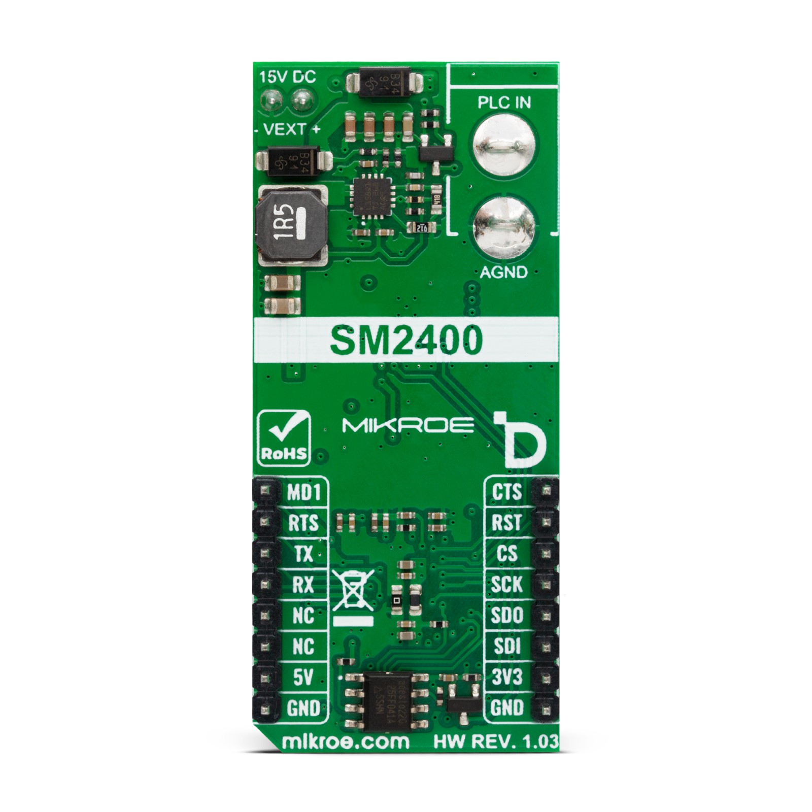
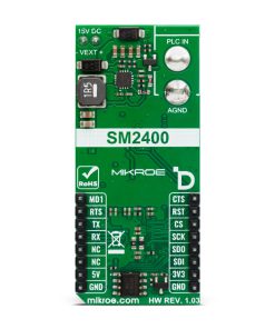
This table shows how the pinout on N-PLC Click corresponds to the pinout on the mikroBUS™ socket (the latter shown in the two middle columns).
Onboard settings and indicators
| Label | Name | Default | Description |
|---|---|---|---|
| LD1 | PWR | – | Power LED Indicator |
| LD2 | PHY | – | Signal Communication LED Indicator |
| LD3 | PLC PWR | – | N-PLC Wall Adapter Connection LED Indicator |
| R49-R51 | – | Unpopulated | SPI Interface Lines Activation Jumpers |
N-PLC Bundle electrical specifications
| Description | Min | Typ | Max | Unit |
|---|---|---|---|---|
| Supply Voltage | 3.3 | – | 5 | V |
| External Power Supply VEXT | – | 15 | – | V |
| Operational Band Range | 5 | – | 500 | kHz |
| Wall Adapter Voltage Range | – | 110/220 | – | VAC |
Software Support
We provide a library for the N-PLC Click as well as a demo application (example), developed using Mikroe compilers. The demo can run on all the main Mikroe development boards.
Package can be downloaded/installed directly from NECTO Studio Package Manager (recommended), downloaded from our LibStock™ or found on Mikroe github account.
Library Description
This library contains API for N-PLC Click driver.
Key functions
-
nplc_set_modeThis function sets operation mode to command or data. -
nplc_generic_writeThis function writes a desired number of data bytes by using UART serial interface. -
nplc_generic_readThis function reads a desired number of data bytes by using UART serial interface.
Example Description
This example demonstrates the use of an N-PLC click boards by showing the communication between the two click boards configured as a receiver and transmitter.
void application_task ( void )
 {
     nplc_process ( );
     if ( app_buf_len > 0 )
     {
         Delay_ms( 500 );
         nplc_process( );
         log_printf( &logger, " Received message: %s", app_buf );
         log_printf( &logger, "rn--------------------------------rn" );
         Delay_ms( 500 );
         log_printf( &logger, " Sending echo response: %s", app_buf );
         nplc_generic_write( &nplc, app_buf, app_buf_len );
         log_printf( &logger, "rn--------------------------------rnn" );
         nplc_clear_app_buf( );
         Delay_ms( 1000 );
     }
 }
The full application code, and ready to use projects can be installed directly from NECTO Studio Package Manager (recommended), downloaded from our LibStock™ or found on Mikroe github account.
Other Mikroe Libraries used in the example:
- MikroSDK.Board
- MikroSDK.Log
- Click.NPLC
Additional notes and informations
Depending on the development board you are using, you may need USB UART click, USB UART 2 Click or RS232 Click to connect to your PC, for development systems with no UART to USB interface available on the board. UART terminal is available in all Mikroe compilers.
mikroSDK
This Click board™ is supported with mikroSDK – Mikroe Software Development Kit, that needs to be downloaded from the LibStock and installed for the compiler you are using to ensure proper operation of mikroSDK compliant Click board™ demo applications.
For more information about mikroSDK, visit the official page.
Resources
Downloads
| Weight | 240 g |
|---|---|
| Brand | MikroElektronika |

