How does it work?
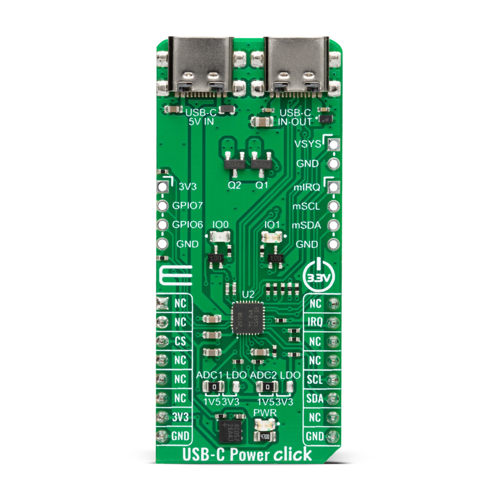
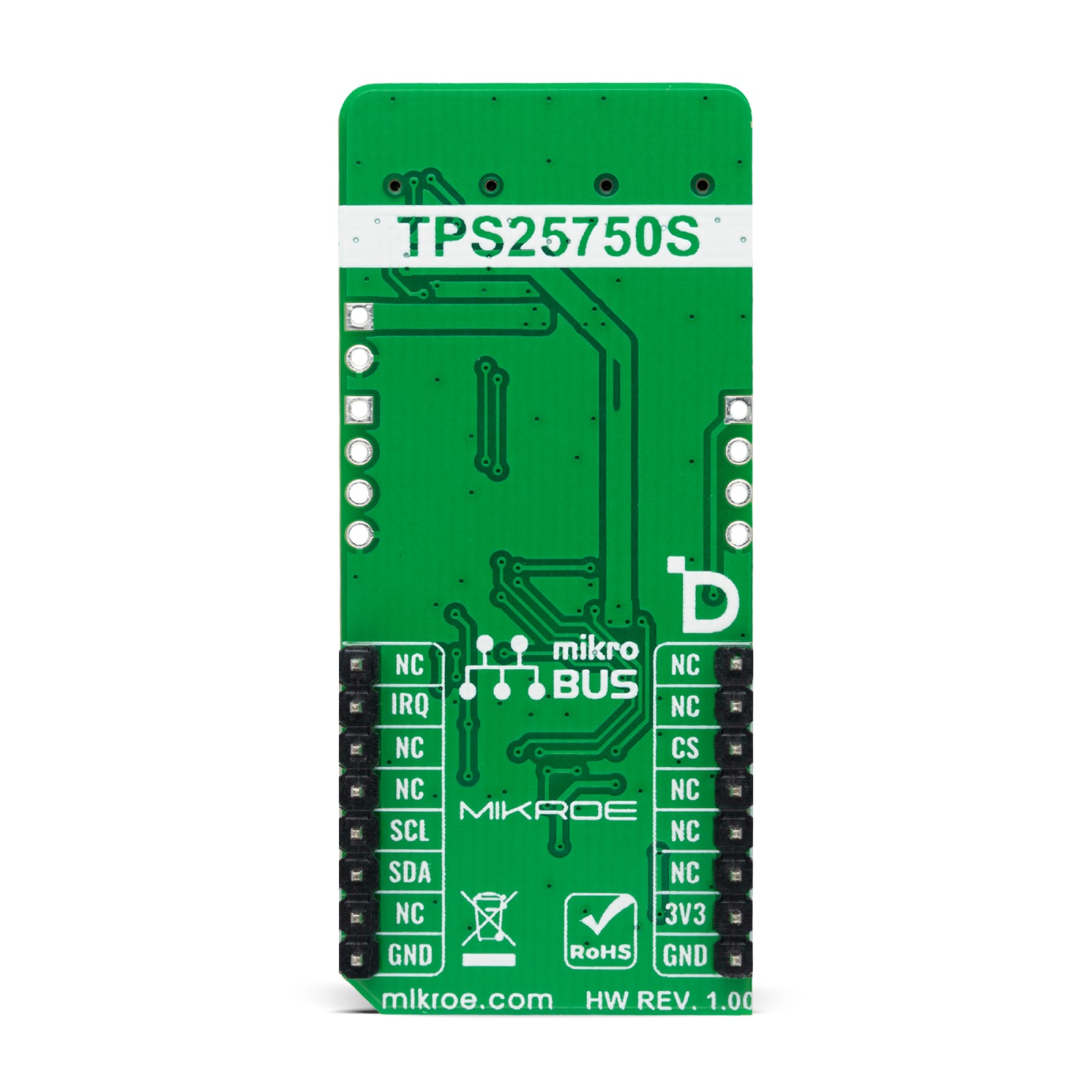
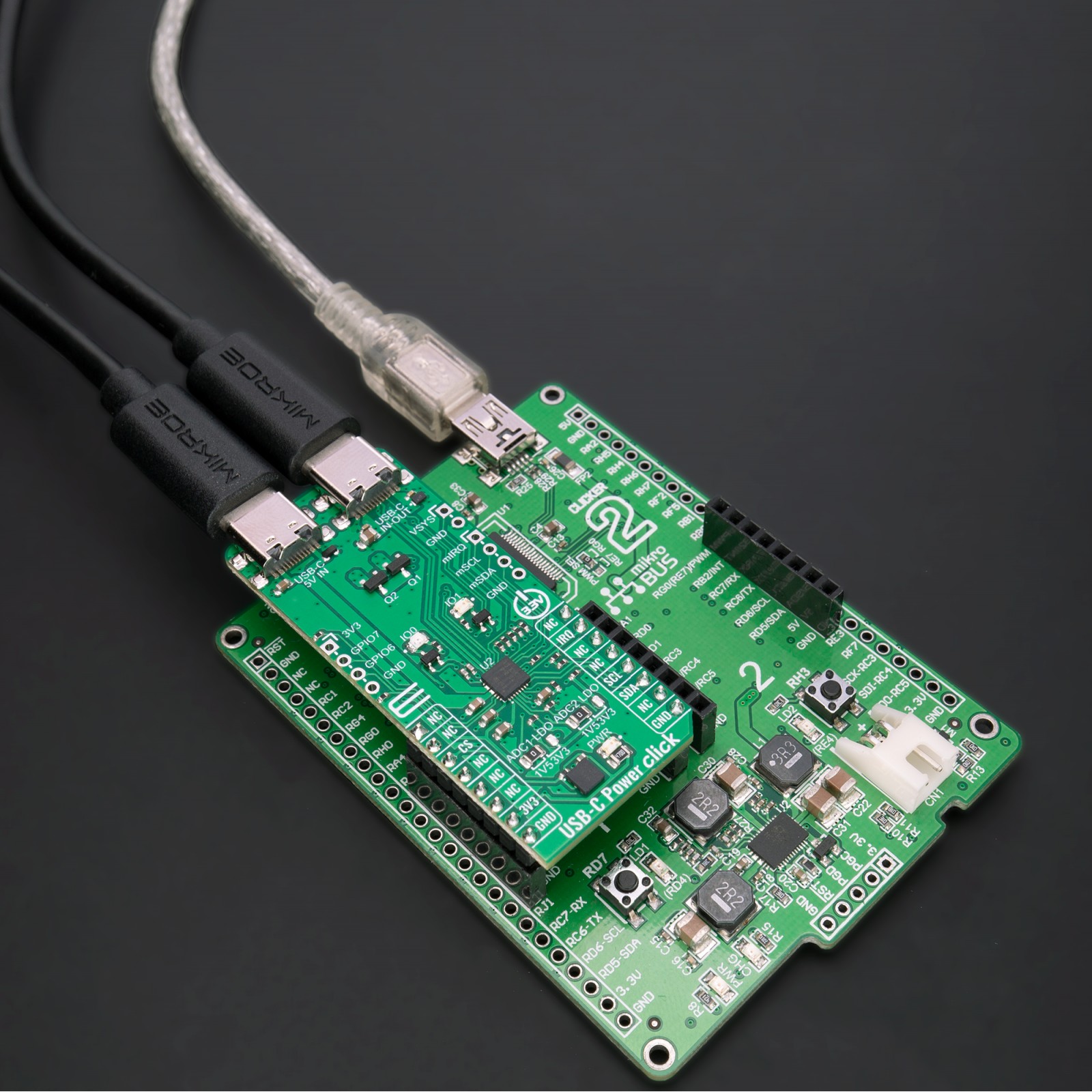
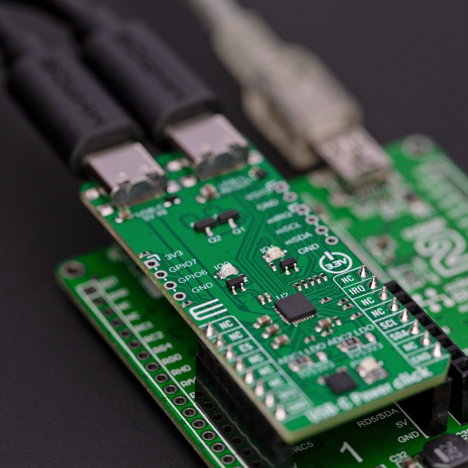
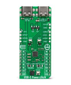
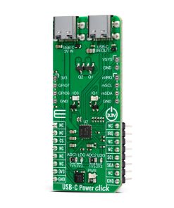
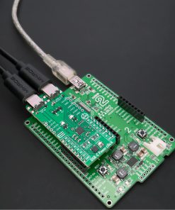
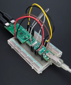
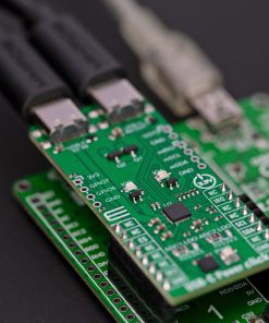
USB-C Power Click is based on the TPS25750S, a USB Type-C and Power Delivery (PD) controller from Texas Instruments, providing cable plug and orientation detection for a single USB Type-C connector. The TPS25750S communicates on the CC wire upon cable detection using the USB PD protocol. When cable detection and USB PD negotiation are complete, the TPS25750S enables the appropriate power path for sourcing or sinking power on the USB IN-OUT connector, depending on the set configuration. The TPS25750S is highly optimized for applications supporting USB-C PD Power and provides robust protection and fully managed internal power paths (5V/3A with 36mΩ sourcing switch). The second USB connector, marked with 5V IN, serves to supply 5V voltage in the form of a USB connection, which is necessary for the internal 5V sourcing power path.
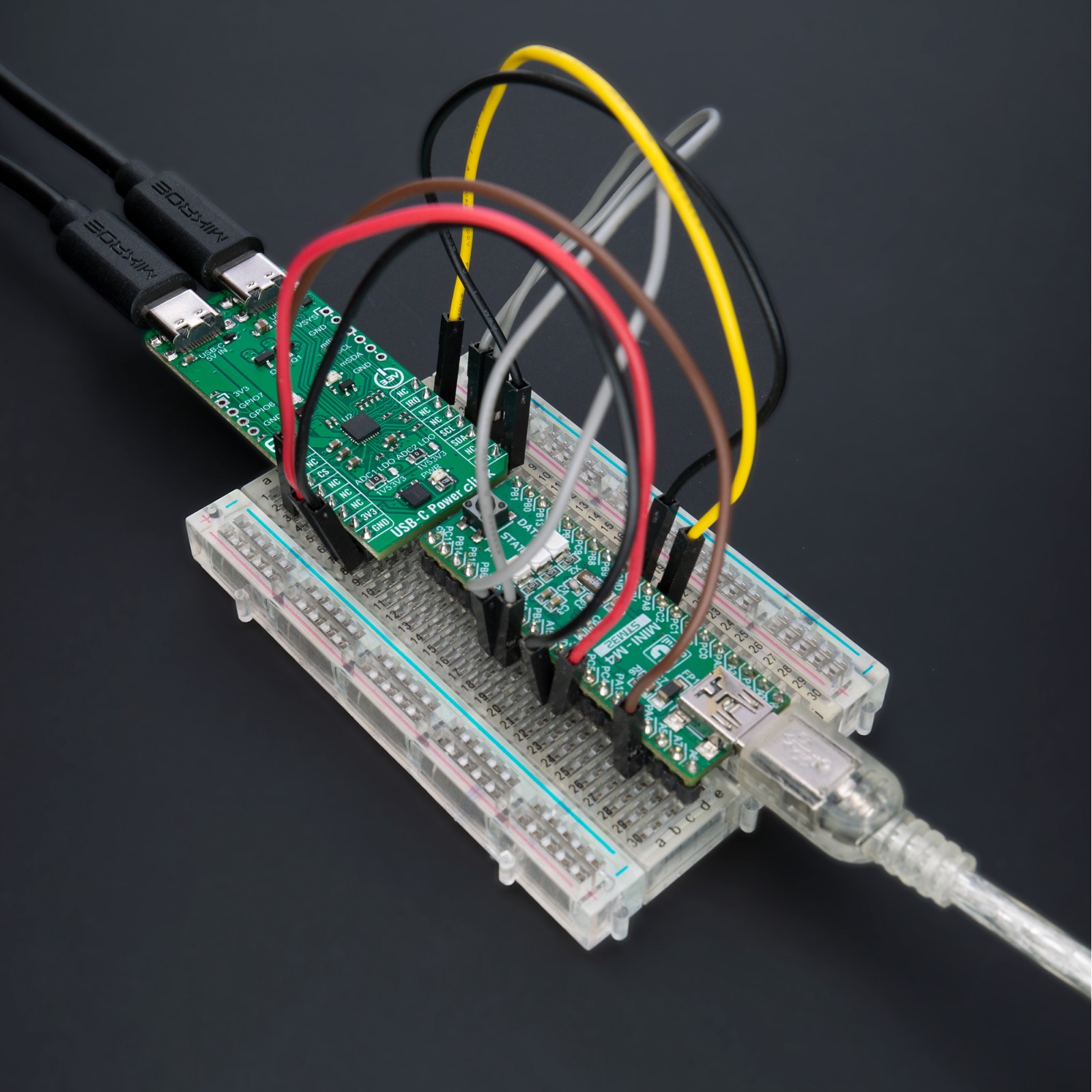
This Click board™ communicates with MCU using the standard I2C 2-Wire interface to read data and configure settings with a maximum frequency of 400kHz. In addition, it also possesses an additional interrupt signal routed on the IRQ pin of the mikroBUS™ socket. Besides the I2C port for communication with the host MCU, the TPS25750S has one additional, I2C interface in Master configuration with a maximum frequency of 400kHz, which will connect to the battery charger like BQ25792 for example (or external EEPROM), to communicate the proper configurations to set it up for charging mode, charging current, OTG mode, and many more. The BQ25792 is a fully integrated switch-mode buck-boost charger for 1-4 cell Li-ion and Li-polymer batteries, allowing users to source or sink high power up to 3A. The necessary power supply and lines for communication with the battery charger are located on unpopulated headers on the right side of the board.
Thanks to the onboard ADC jumpers, the TPS25750S can set the dead battery configuration and the I2C slave address for the PD controller based on their position. Two offered dead battery configurations are Safe mode and Always Enable Sink. The Safe mode does not enable the sink path, and USB PD is disabled until the configuration is loaded. In the Always Enable Sink mode, the device enables the sink path, regardless of the current amount the attached source offers. The USB PD is disabled until the configuration is loaded. Please consult the attached datasheet for more information about device configuration using these jumpers.
This Click board™ also features two GPIO signals, located on unpopulated headers, that are user-defined for status and control information. GPIO pins can be mapped to USB Type-C, USB PD, and application-specific events to control other ICs, interrupt a host processor, or receive input from other ICs. Along with the GPIOs, it also has two LED indicators, IO0 and IO1, for the realization of visual detection of some anomalies or statuses during operation.
This Click board™ can only be operated with a 3.3V logic voltage level. The board must perform appropriate logic voltage level conversion before using MCUs with different logic levels. However, the Click board™ comes equipped with a library containing functions and an example code that can be used as a reference for further development.
TPS25750 Config Tool
Although it comes with pre-configured firmware, the TPS25750S can be configured using the TPS25750 Application Customization Tool, a web-based GUI, for the application-specific PD charging architecture requirements and data roles. The tool may be launched either through a web browser or as a native application and provides users with capabilities like generating new configuration settings, loading configuration settings to a device, and saving configuration settings in JSON format. You can find a detailed explanation and the tool’s use principle in the TPS25750 Application Customization Tool User’s Guide.
Specifications
Type
USB-C PD
Applications
Can be used for applications supporting USB-C PD Power like power tools, power banks, retail automation, and other personal electronics and industrial applications
On-board modules
TPS25750S – USB Type-C and Power Delivery (PD) controller from Texas Instruments
Key Features
Integrated fully managed power paths, robust power path protection, optimized for power applications, I2C control for TI battery chargers, web-based GUI and pre-configured firmware, user-configurable GPIOs and LED indicators, and more
Interface
I2C
Feature
ClickID
Compatibility
mikroBUS™
Click board size
L (57.15 x 25.4 mm)
Input Voltage
3.3V
Pinout diagram
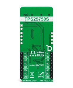
This table shows how the pinout on USB-C Power Click corresponds to the pinout on the mikroBUS™ socket (the latter shown in the two middle columns).
Onboard settings and indicators
Label | Name | Default | Description |
---|---|---|---|
LD1 | PWR | – | Power LED Indicator |
LD2-LD3 | IO0-IO1 | – | User-Configurable LED Indicators |
JP1-JP2 | ADC LDO | Left | Device Configuration/I2C Address Selection 1V5/3V3: Left position 1V5, Right position 3V3 |
J1 | GP | Unpopulated | User-Configurable I/O Pins |
J2 | I2Cm | Unpopulated | External IC I2C Master Control Pins |
J3 | VSYS | Unpopulated | External IC Power Supply Pin |
USB-C Power Click electrical specifications
Description | Min | Typ | Max | Unit |
---|---|---|---|---|
Supply Voltage | – | 3.3 | – | V |
Input Voltage | – | 5 | – | V |
Output Current | – | – | 3 | A |
Software Support
We provide a library for the USB-C Power Click as well as a demo application (example), developed using Mikroe compilers. The demo can run on all the main Mikroe development boards.
Package can be downloaded/installed directly from NECTO Studio Package Manager (recommended), downloaded from our LibStock™ or found on Mikroe github account.
Library Description
This library contains API for USB-C Power Click driver.
Key functions
-
usbcpower_get_status
USB-C Power gets status function. -
usbcpower_get_pwr_status
USB-C Power gets PWR status function. -
usbcpower_start_patch_burst_mode
USB-C Power starts the patch burst mode function.
Example Description
This library contains API for the USB-C Power Click driver. The library initializes and defines the I2C bus drivers to write and read data from registers. The library also includes a function for patch bundle update tasks.
void application_task ( void )
{
if ( USBCPOWER_OK == usbcpower_get_status( &usbcpower, &status ) )
{
if ( USBCPOWER_OK == usbcpower_get_pwr_status( &usbcpower, &pwr_status ) )
{
usbcpower_display_status( );
log_printf( &logger, "- - - - - - - - - - - - - - -rn" );
usbcpower_display_pwr_status( );
log_printf( &logger, "-----------------------------rn" );
}
}
Delay_ms( 3000 );
}
The full application code, and ready to use projects can be installed directly from NECTO Studio Package Manager (recommended), downloaded from our LibStock™ or found on Mikroe github account.
Other Mikroe Libraries used in the example:
- MikroSDK.Board
- MikroSDK.Log
- Click.USBCPower
Additional notes and informations
Depending on the development board you are using, you may need USB UART click, USB UART 2 Click or RS232 Click to connect to your PC, for development systems with no UART to USB interface available on the board. UART terminal is available in all Mikroe compilers.
mikroSDK
This Click board™ is supported with mikroSDK – Mikroe Software Development Kit, that needs to be downloaded from the LibStock and installed for the compiler you are using to ensure proper operation of mikroSDK compliant Click board™ demo applications.
For more information about mikroSDK, visit the official page.