How does it work?
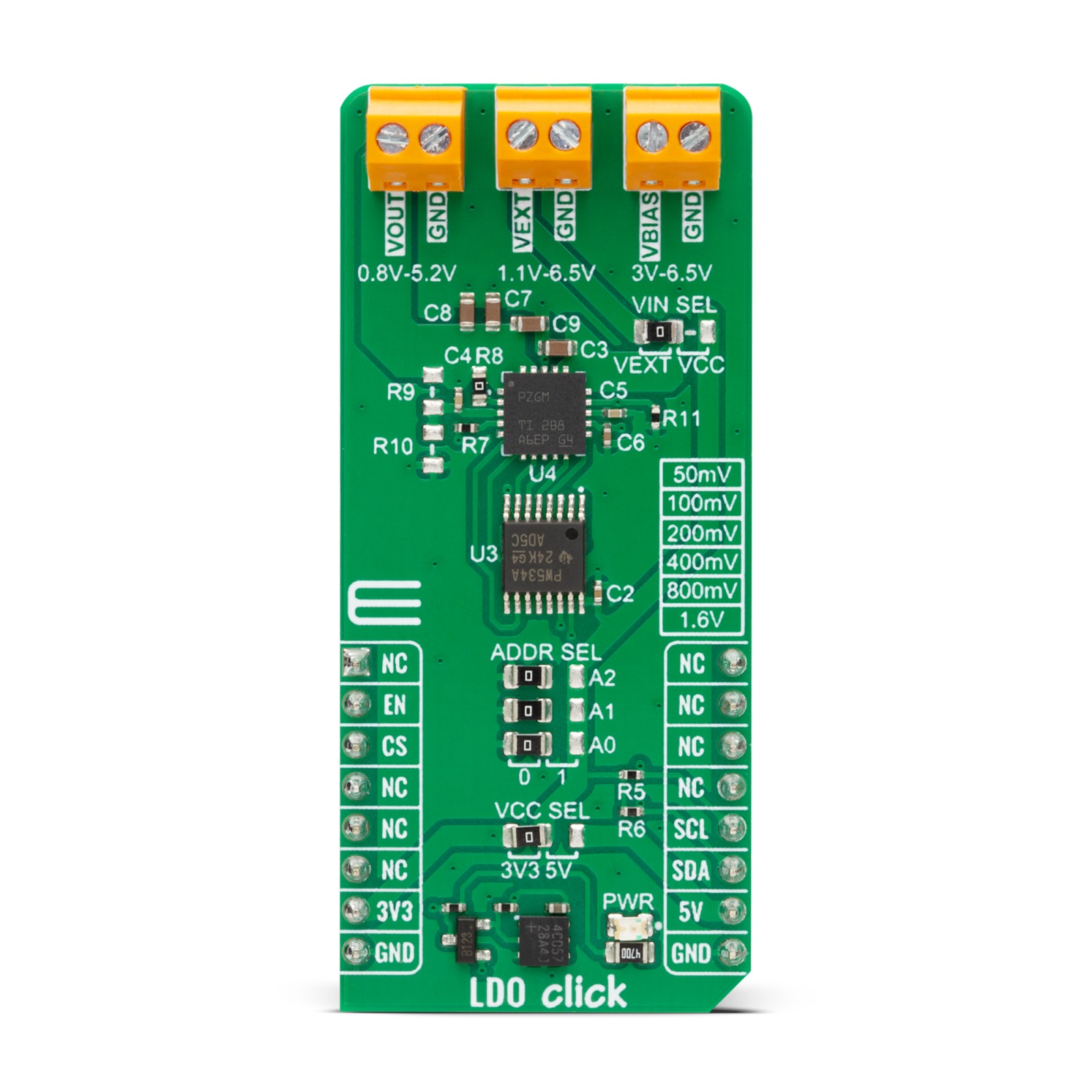
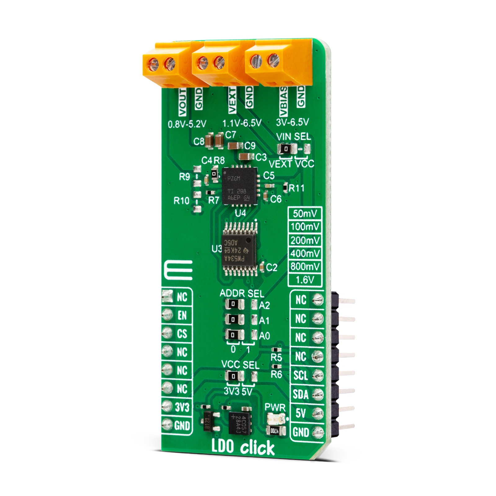
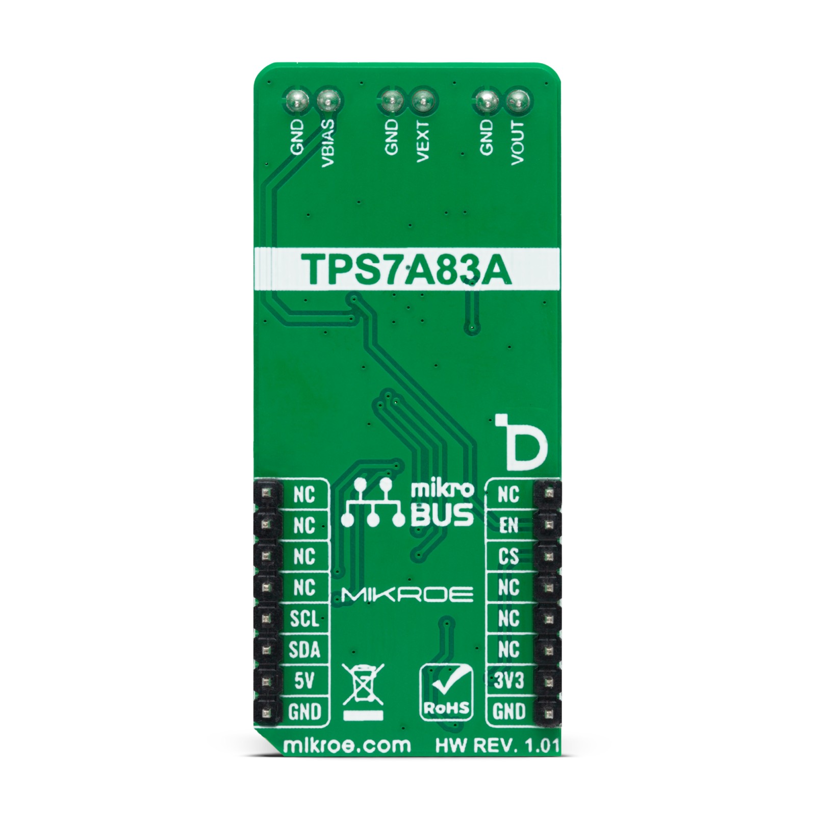
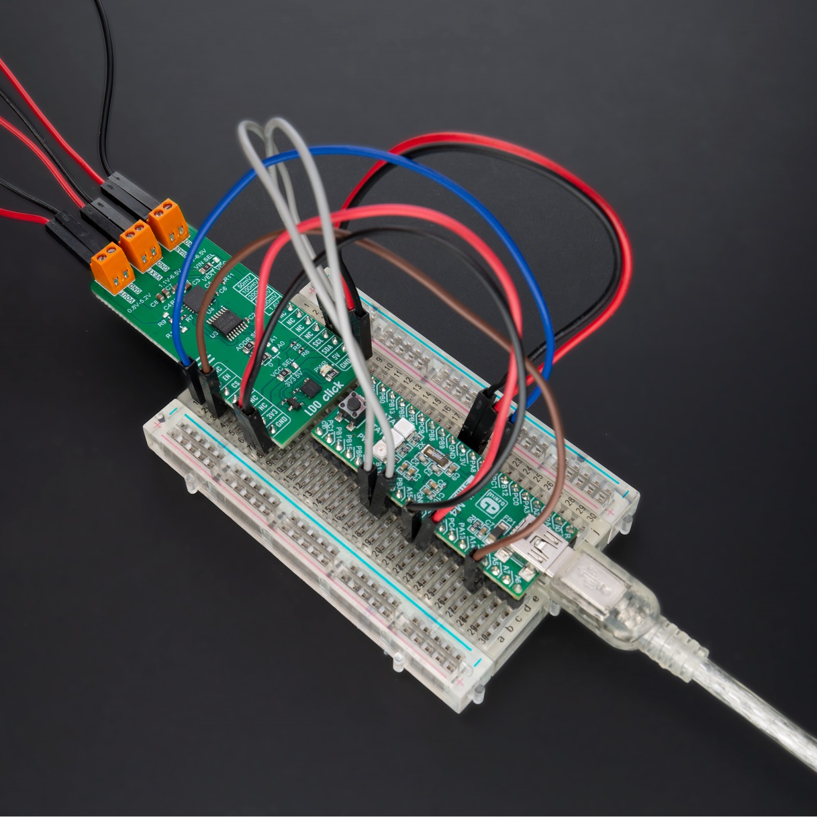
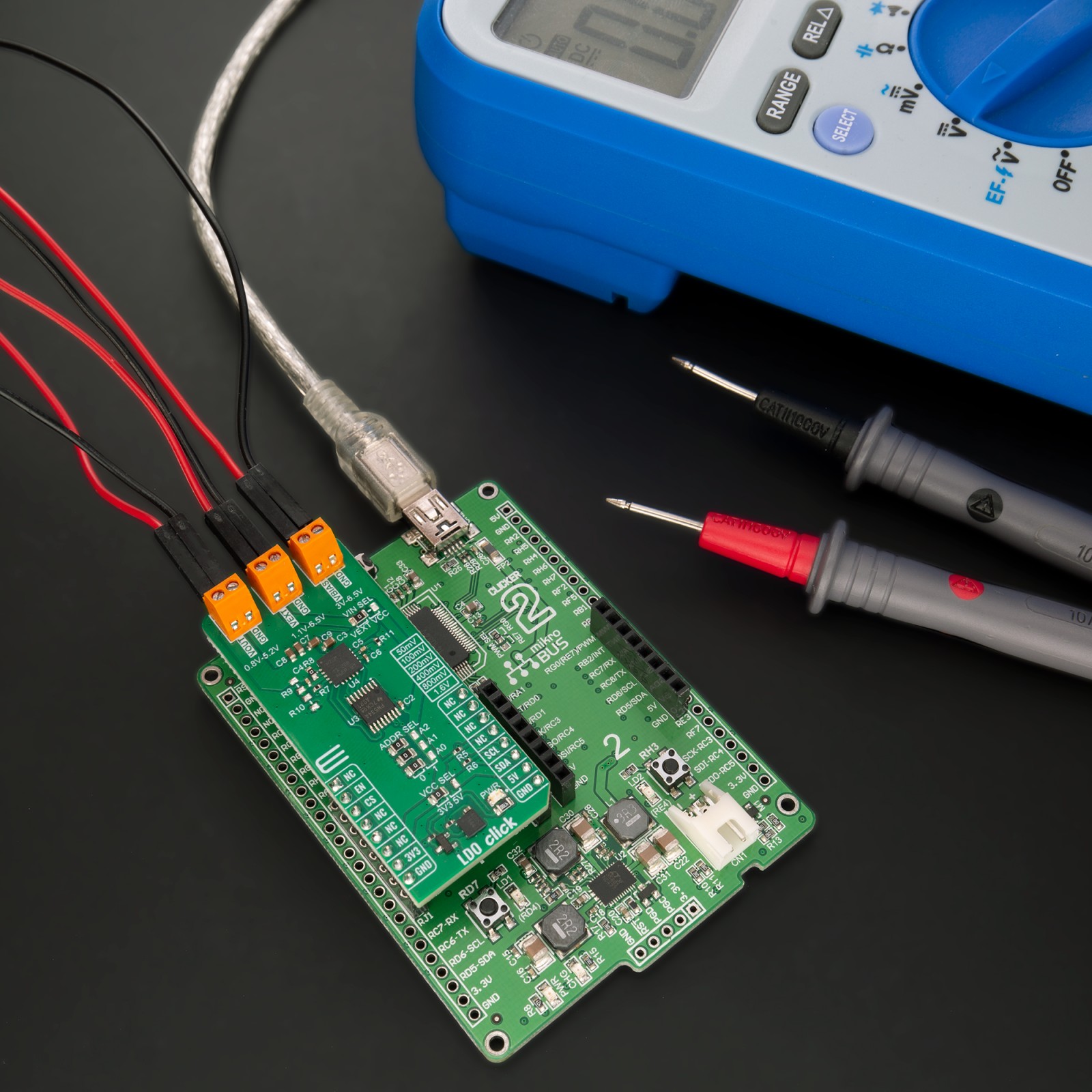
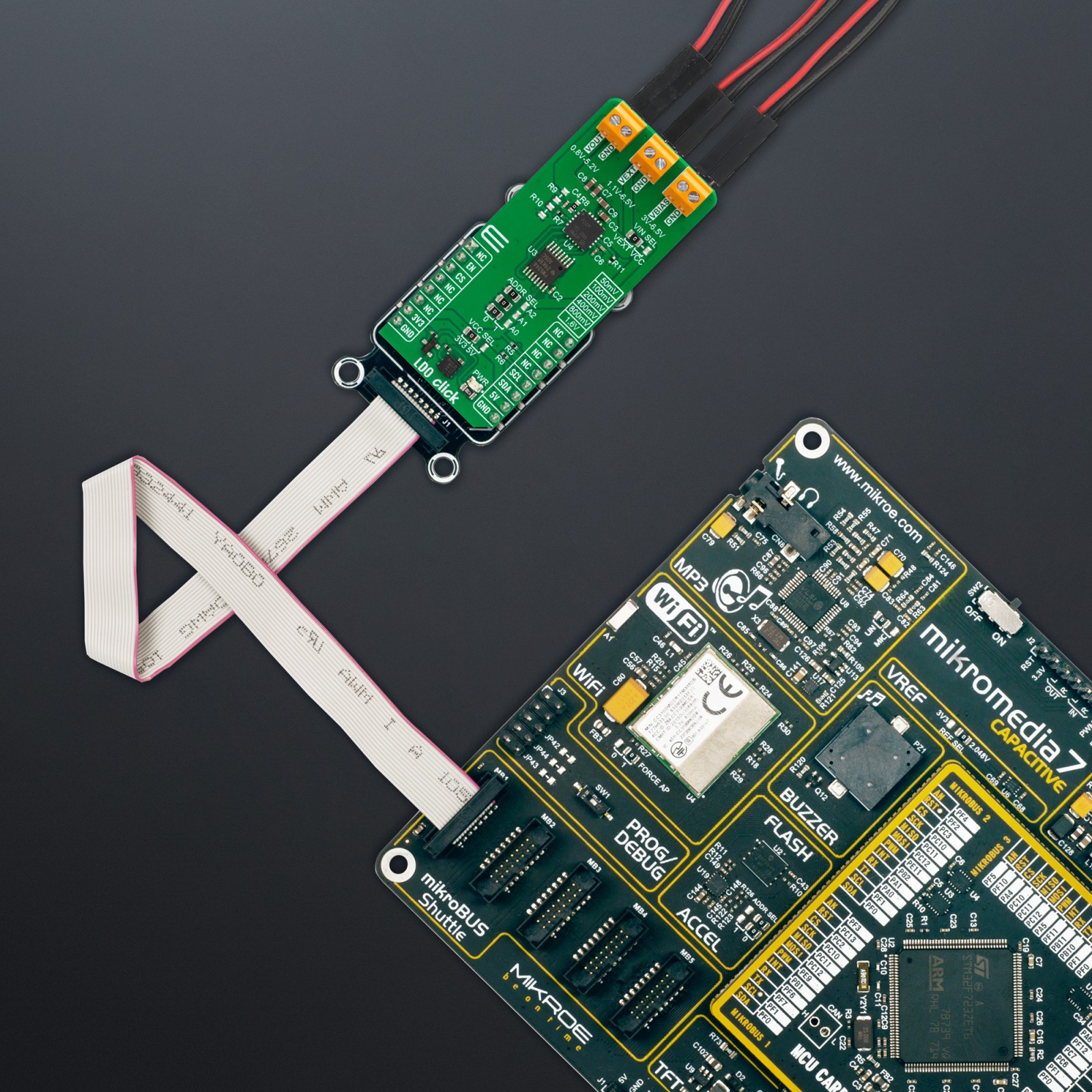
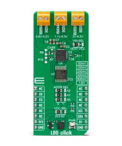
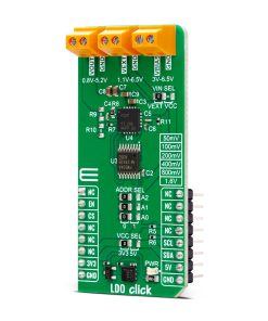
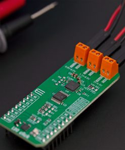
LDO Click is based on the TPS7A83A, a high-current (2A), low-noise, high-accuracy, and low-dropout linear voltage regulator from Texas Instruments. The TPS7A83A has several features that make it useful in various applications, like high accuracy, high-PSR output, and fast transient response for voltage regulation part, as well as certain internal protections like thermal shutdown and foldback current limit. All these features make this Click board™ a robust solution for many challenging problems in generating a clean, accurate power supply.
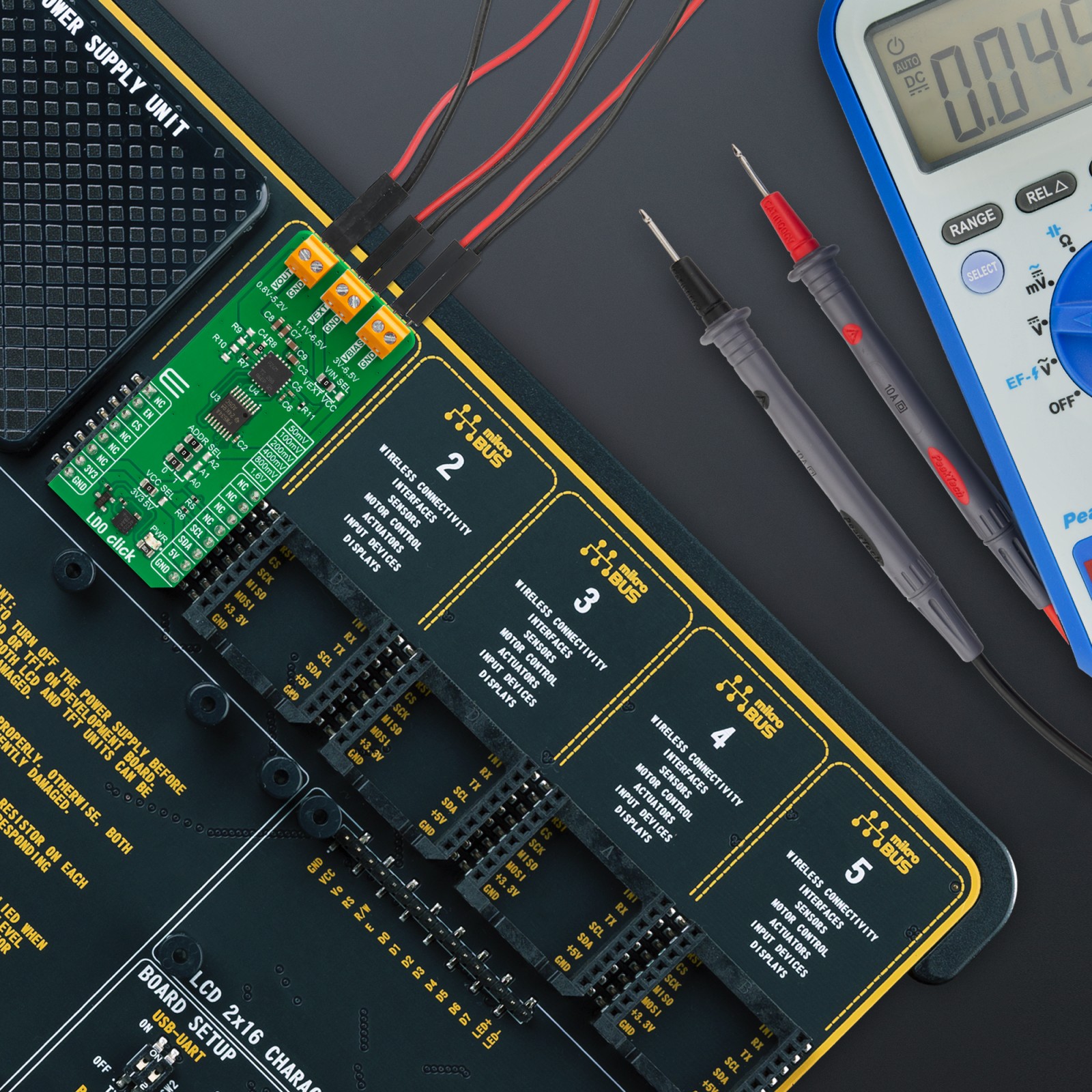
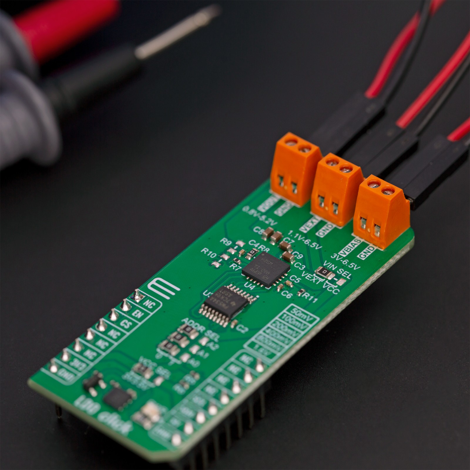
The TPS7A8300A can be easily enabled using the EN pin of the mikroBUS™ socket, offering a switch operation to turn ON/OFF the TPS7A8300A. It has a pin-programmable output voltage from 0.8V-3.95V with a 50mV resolution, or it can be adjustable from 0.8V-5.2V using an external resistor divider (R9 and R10). The pin-programmable output voltage is possible thanks to the TCA9534A, an I2C-configurable I/O expander also from Texas Instruments, which by setting the appropriate voltage setting pins on the TPS7A83A, which are connected to an internal feedback network, programs the regulated output voltage.
The TCA9534A expander also can choose the least significant bit (LSB) of its I2C slave address by positioning SMD jumpers labeled as ADDR SEL to an appropriate position marked as 0 and 1. The adjustable output voltage is achieved through voltage divider resistors whose corresponding values can be found in the datasheet table.
One of the power terminals on the board is the VBIAS terminal, which minimizes the internal charge-pump noise when the internal voltage is clamped, thereby reducing the overall output noise floor. This rail enables the use of low-input voltage, low-output (LILO) voltage conditions (VEXT=1.2V, VOUT =1V) to reduce the power dissipation of the TPS7A8300A. Using a VBIAS voltage improves DC and AC performance for VEXT≤2.2V.
This Click board™ can operate with either 3.3V or 5V logic voltage levels selected via the VCC SEL jumper. This way, it is allowed for both 3.3V and 5V capable MCUs to use the communication lines properly. Additionally, there is a possibility for the TPS7A83A power supply selection via jumper labeled as VIN SEL to supply the TPS7A83A from an external power supply terminal in the range from 1.1V to 6.5V or with selected mikroBUS™ power rail. However, the Click board™ comes equipped with a library containing easy-to-use functions and an example code that can be used, as a reference, for further development.
Specifications
Type
Buck,Linear
Applications
Can be used to power noise-sensitive components such as serializer and deserializer, ADCs, DACs, and RF components
On-board modules
TPS7A83A – low-dropout linear regulator from Texas Instruments
Key Features
High accuracy, low output voltage noise, wide input voltage range, pin-programmable and adjustable output voltage, excellent load transient response, bias supply to improve performance, and more
Interface
I2C
Feature
ClickID
Compatibility
mikroBUS™
Click board size
L (57.15 x 25.4 mm)
Input Voltage
3.3V or 5V
Pinout diagram
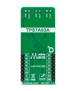
This table shows how the pinout on LDO Click corresponds to the pinout on the mikroBUS™ socket (the latter shown in the two middle columns).
Onboard settings and indicators
Label | Name | Default | Description |
---|---|---|---|
LD1 | PWR | – | Power LED Indicator |
JP1-JP3 | ADDR SEL | Left | I2C Address Selection 0/1: Left position 0, Right position 1 |
JP4 | VIN SEL | Right | TPS7A83A Power Supply Selection VEXT/VCC: Left position VEXT, Right position VCC |
JP5 | VCC SEL | Left | Logic Level Voltage Selection 3V3/5V: Left position 3V3, Right position 5V |
R9-R10 | R9-R10 | Unpopulated | Adjustable Output Voltage Resistors |
LDO Click electrical specifications
Description | Min | Typ | Max | Unit |
---|---|---|---|---|
Supply Voltage | 3.3 | – | 5 | V |
External Power Supply VEXT | 1.1 | – | 6.5 | V |
External Bias Supply | 3 | – | 6.5 | V |
Output Voltage | 0.8 | – | 5.2 | V |
Output Current | – | – | 2 | A |
Software Support
We provide a library for the LDO Click as well as a demo application (example), developed using Mikroe compilers. The demo can run on all the main Mikroe development boards.
Package can be downloaded/installed directly from NECTO Studio Package Manager (recommended), downloaded from our LibStock™ or found on Mikroe github account.
Library Description
This library contains API for LDO Click driver.
Key functions
-
ldo_enable_device
This function enables the device by setting the EN pin to HIGH logic state. -
ldo_disable_device
This function disables the device by setting the EN pin to LOW logic state. -
ldo_set_vout
This function sets the voltage output.
Example Description
This example demonstrates the use of LDO click by changing the output voltage.
void application_task ( void )
{
static uint16_t vout = LDO_VOUT_MIN;
if ( LDO_OK == ldo_set_vout ( &ldo, vout ) )
{
log_printf ( &logger, " VOUT: %u mVrnn", vout );
}
vout += LDO_VOUT_STEP;
if ( vout > LDO_VOUT_MAX )
{
vout = LDO_VOUT_MIN;
}
Delay_ms ( 3000 );
}
The full application code, and ready to use projects can be installed directly from NECTO Studio Package Manager (recommended), downloaded from our LibStock™ or found on Mikroe github account.
Other Mikroe Libraries used in the example:
- MikroSDK.Board
- MikroSDK.Log
- Click.LDO
Additional notes and informations
Depending on the development board you are using, you may need USB UART click, USB UART 2 Click or RS232 Click to connect to your PC, for development systems with no UART to USB interface available on the board. UART terminal is available in all Mikroe compilers.
mikroSDK
This Click board™ is supported with mikroSDK – Mikroe Software Development Kit, that needs to be downloaded from the LibStock and installed for the compiler you are using to ensure proper operation of mikroSDK compliant Click board™ demo applications.
For more information about mikroSDK, visit the official page.