How does it work?
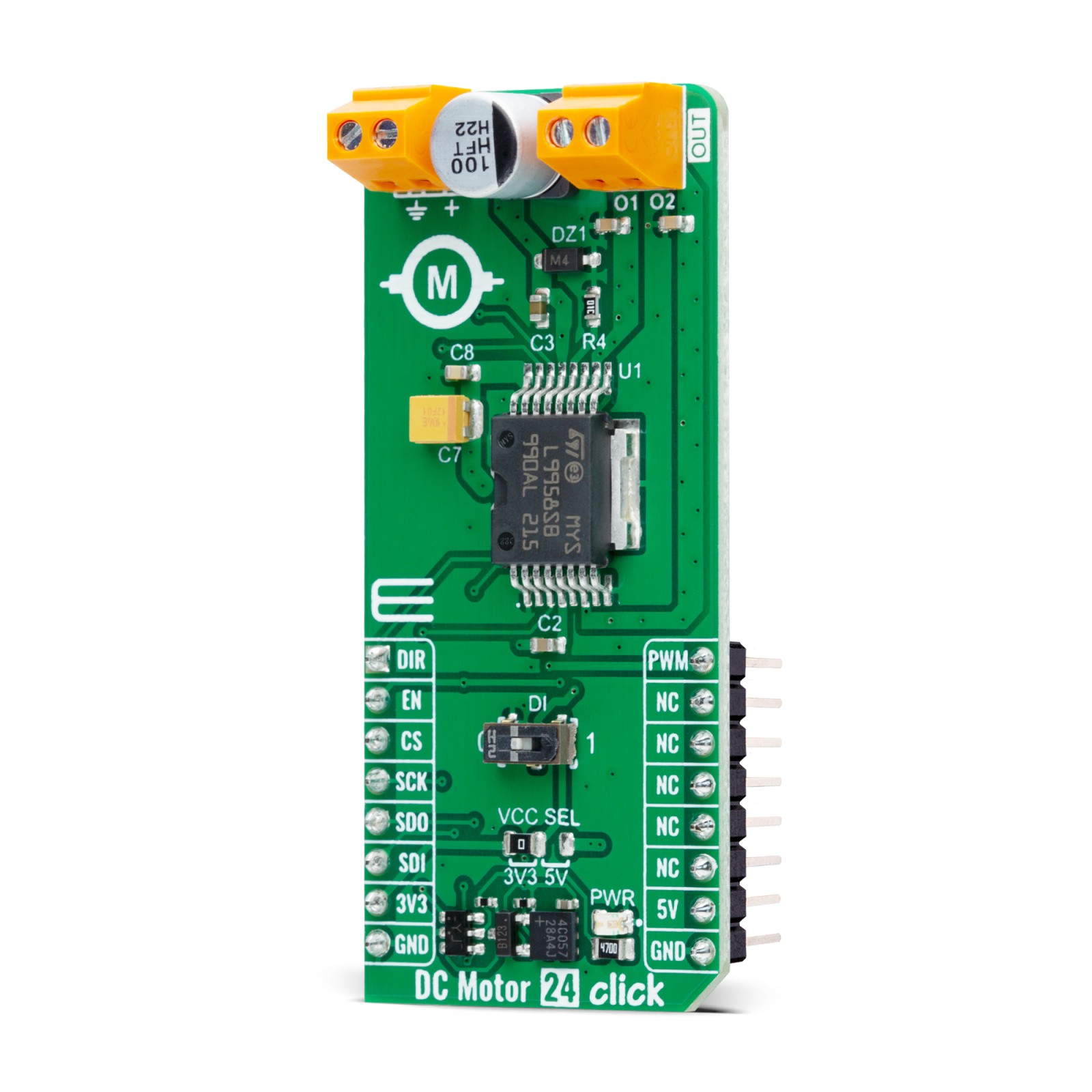
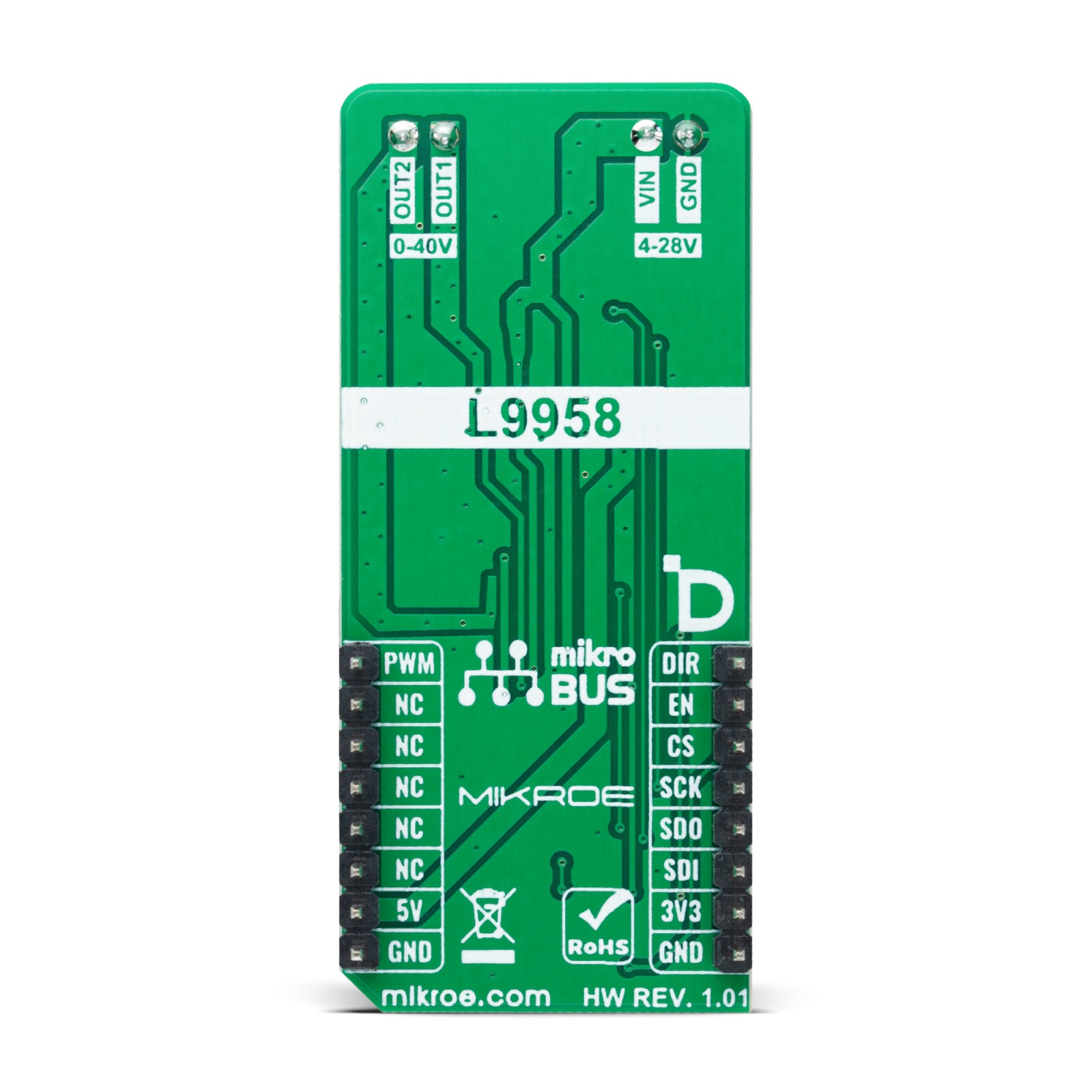
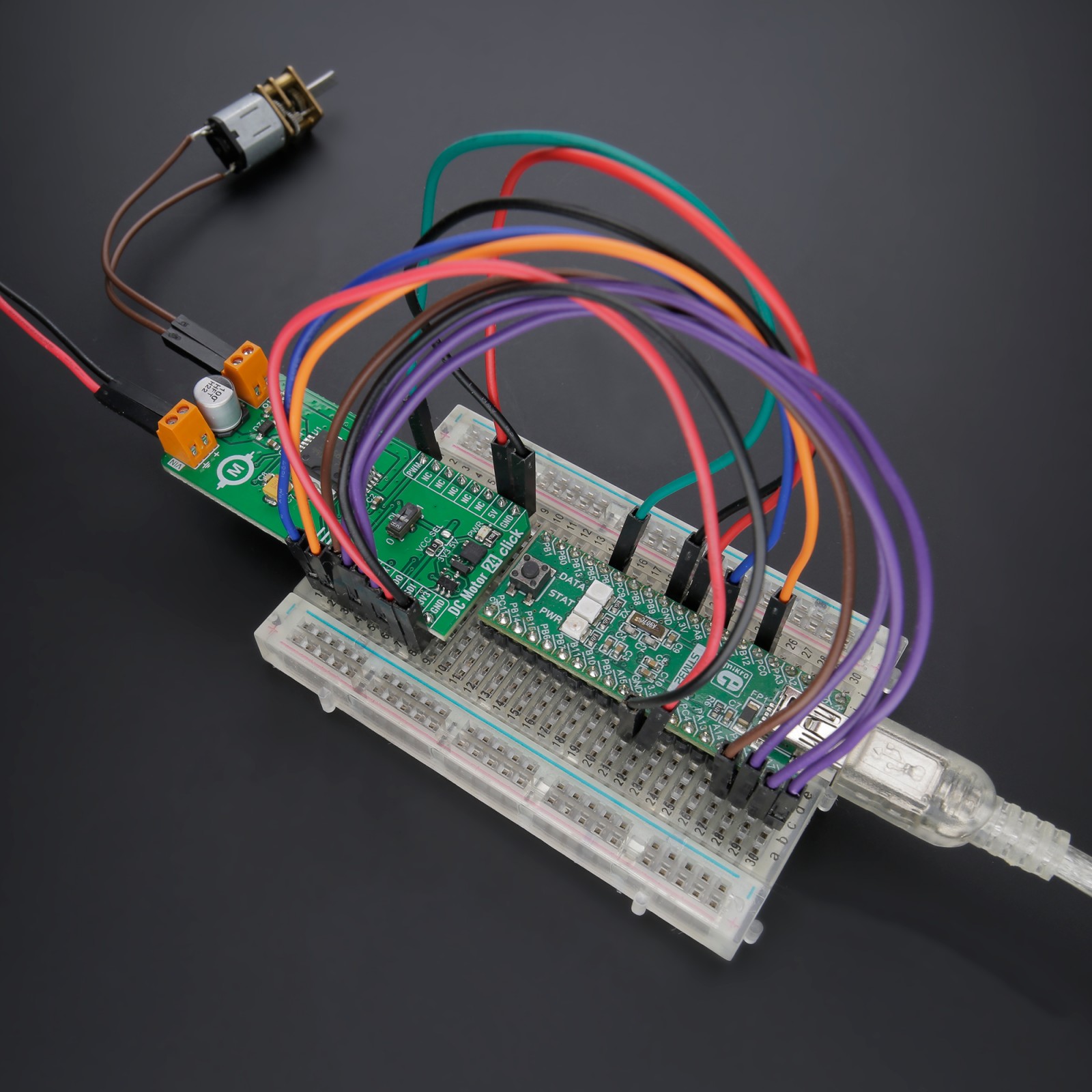
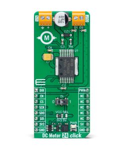
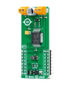
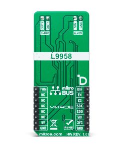
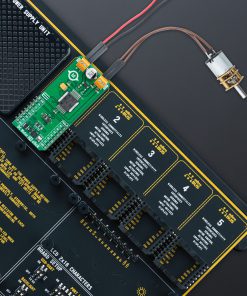
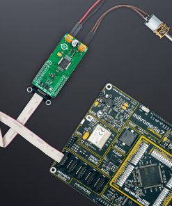
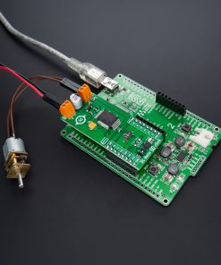
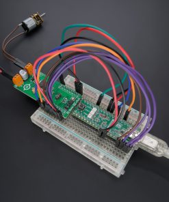
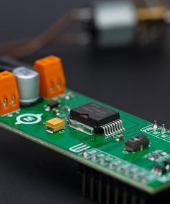
DC Motor 24 Click is based on the L9958, a fully integrated motor driver for DC and stepper motors from STMicroelectronics used in safety-critical applications and under extreme environmental conditions. This Click board™ provides all the input and output capabilities necessary to drive DC or stepper motors (OUT terminal), alongside monitor diagnostic functions. The L9958 is rated for an operating voltage range from 4V to 28V (VIN terminal), with direct PWM motor control. The PWM control with simple direction control, DIR pin routed to the AN pin on the mikroBUS™ socket, allows MCU to manage the direction of the DC motor (clockwise or counterclockwise). This combination enables highly efficient motor drive output, ensuring reliable operation for highly competitive automotive applications.
This Click board™ communicates with MCU using a 4-wire SPI-compatible interface with a maximum frequency of 5MHz, for the configuration of the L9958. The SPI interface can set the current regulation threshold from 2.5A to 8.6A, typically in four steps (6.6A is a default). The L9958 also has detailed failure diagnostics on each channel provided via the SPI interface. The H-bridge is protected against temperature and short circuits and has an undervoltage/ overvoltage lockout for all the supply voltages. All malfunctions cause the output stages to go tri-state.
The output can be disabled (set to tri-state) via a combination of logic states of an onboard switch labeled as DI and enable pin routed to the EN pin on the mikroBUS™ socket. The internal H-bridge also contains integrated free-wheel diodes. In the case of the free-wheeling condition, the low-side transistor is switched ON in parallel to its diode to reduce power dissipation.
This Click board™ can operate with either 3.3V or 5V logic voltage levels selected via the VCC SEL jumper. This way, both 3.3V and 5V capable MCUs can use the communication lines properly. However, the Click board™ comes equipped with a library containing easy-to-use functions and an example code that can be used, as a reference, for further development.
Specifications
Type
Brushed
Applications
Can be used for controlling DC and stepper motors in safety-critical automotive applications and under extreme environmental conditions
On-board modules
L9958 – fully integrated motor driver for DC and stepper motors from STMicroelectronics
Key Features
SPI-programmable current threshold, direct PWM control, selectable motor direction, freewheeling condition, full protection and diagnostics, and more
Interface
PWM,SPI
Feature
ClickID
Compatibility
mikroBUS™
Click board size
L (57.15 x 25.4 mm)
Input Voltage
3.3V or 5V
Pinout diagram
This table shows how the pinout on DC Motor 24 Click corresponds to the pinout on the mikroBUS™ socket (the latter shown in the two middle columns).
Onboard settings and indicators
Label | Name | Default | Description |
---|---|---|---|
LD1 | PWR | – | Power LED Indicator |
JP1 | VCC SEL | Left | Logic Level Voltage Selection 3V3/5V: Left position 3V3, Right position 5V |
SW1 | DI | Left | H-Bridge Control 0/1: Left position 0, Right position 1 |
DC Motor 24 Click electrical specifications
Description | Min | Typ | Max | Unit |
---|---|---|---|---|
Supply Voltage | 3.3 | – | 5 | V |
External Supply Voltage | 4 | – | 28 | V |
Output Current | 2.5 | – | 8.6 | A |
Software Support
We provide a library for the DC Motor 24 Click as well as a demo application (example), developed using Mikroe compilers. The demo can run on all the main Mikroe development boards.
Package can be downloaded/installed directly from NECTO Studio Package Manager (recommended), downloaded from our LibStock™ or found on Mikroe github account.
Library Description
This library contains API for DC Motor 24 Click driver.
Key functions
-
dcmotor24_read_diag
This function reads a diagnostics word by using SPI serial interface. -
dcmotor24_switch_direction
This function switches the direction by toggling the DIR pin state. -
dcmotor24_set_duty_cycle
This function sets the PWM duty cycle in percentages ( Range[ 0..1 ] ).
Example Description
This example demonstrates the use of the DC Motor 24 Click board™ by driving the motor in both directions at different speeds.
void application_task ( void )
{
static int8_t duty_pct = 10;
static int8_t duty_step = 10;
uint16_t diag;
if ( DCMOTOR24_OK == dcmotor24_set_duty_cycle ( &dcmotor24, ( float ) duty_pct / 100 ) )
{
log_printf( &logger, "rn Duty: %u%%rn", ( uint16_t ) duty_pct );
}
if ( DCMOTOR24_OK == dcmotor24_read_diag ( &dcmotor24, &diag ) )
{
dcmotor24_display_diag ( diag );
}
Delay_ms( 500 );
if ( ( 100 == duty_pct ) || ( 0 == duty_pct ) )
{
duty_step = -duty_step;
if ( 0 == duty_pct )
{
log_printf( &logger, "rn Switch directionrn" );
dcmotor24_switch_direction ( &dcmotor24 );
Delay_ms ( 500 );
}
}
duty_pct += duty_step;
}
The full application code, and ready to use projects can be installed directly from NECTO Studio Package Manager (recommended), downloaded from our LibStock™ or found on Mikroe github account.
Other Mikroe Libraries used in the example:
- MikroSDK.Board
- MikroSDK.Log
- Click.DCMotor24
Additional notes and informations
Depending on the development board you are using, you may need USB UART click, USB UART 2 Click or RS232 Click to connect to your PC, for development systems with no UART to USB interface available on the board. UART terminal is available in all Mikroe compilers.
mikroSDK
This Click board™ is supported with mikroSDK – Mikroe Software Development Kit. To ensure proper operation of mikroSDK compliant Click board™ demo applications, mikroSDK should be downloaded from the LibStock and installed for the compiler you are using.
For more information about mikroSDK, visit the official page.