How does it work?
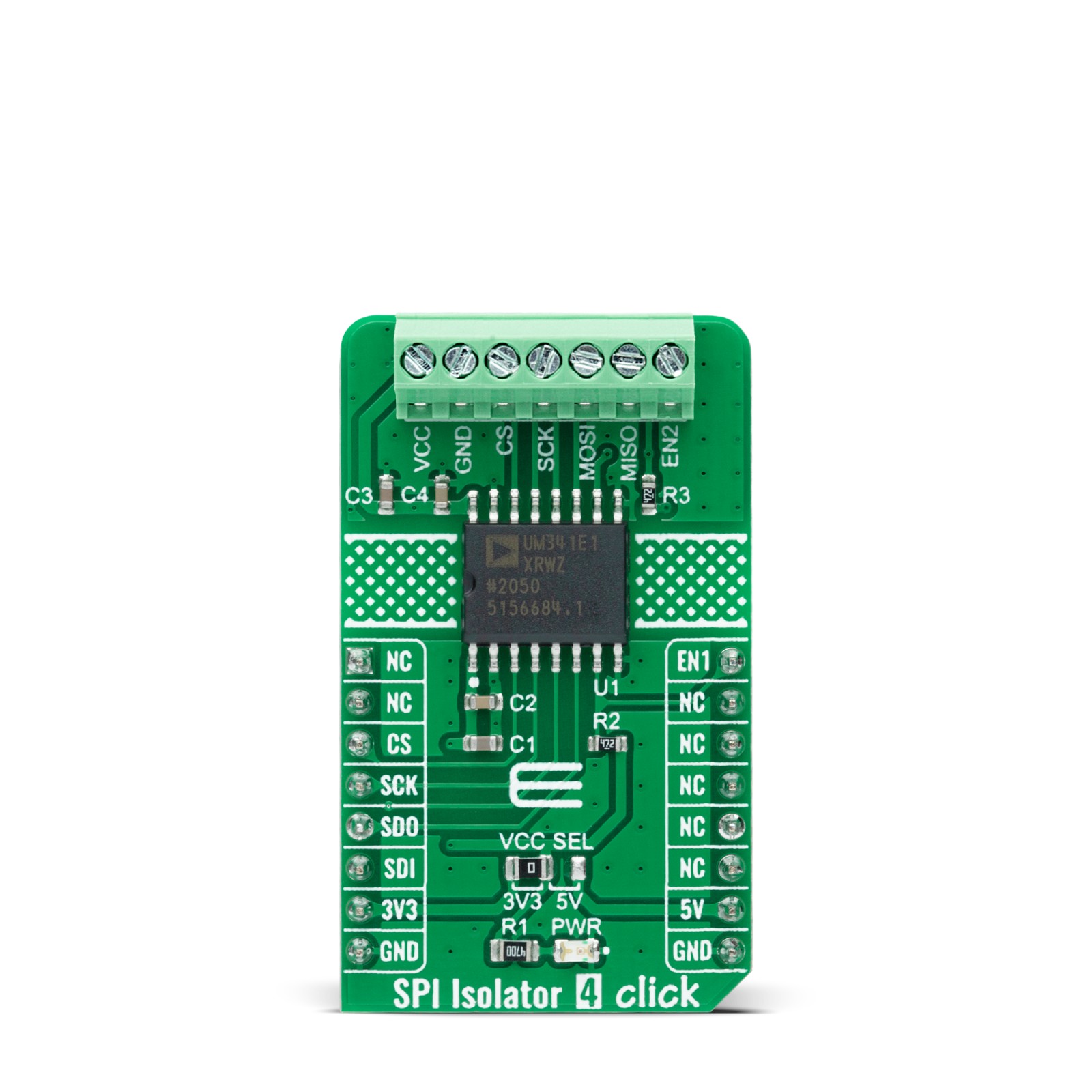
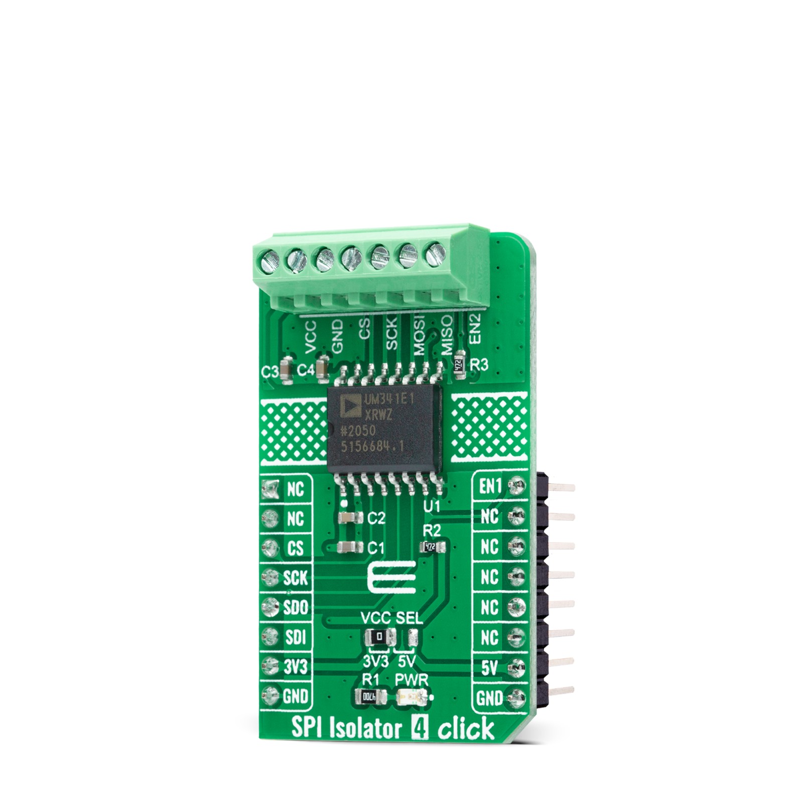
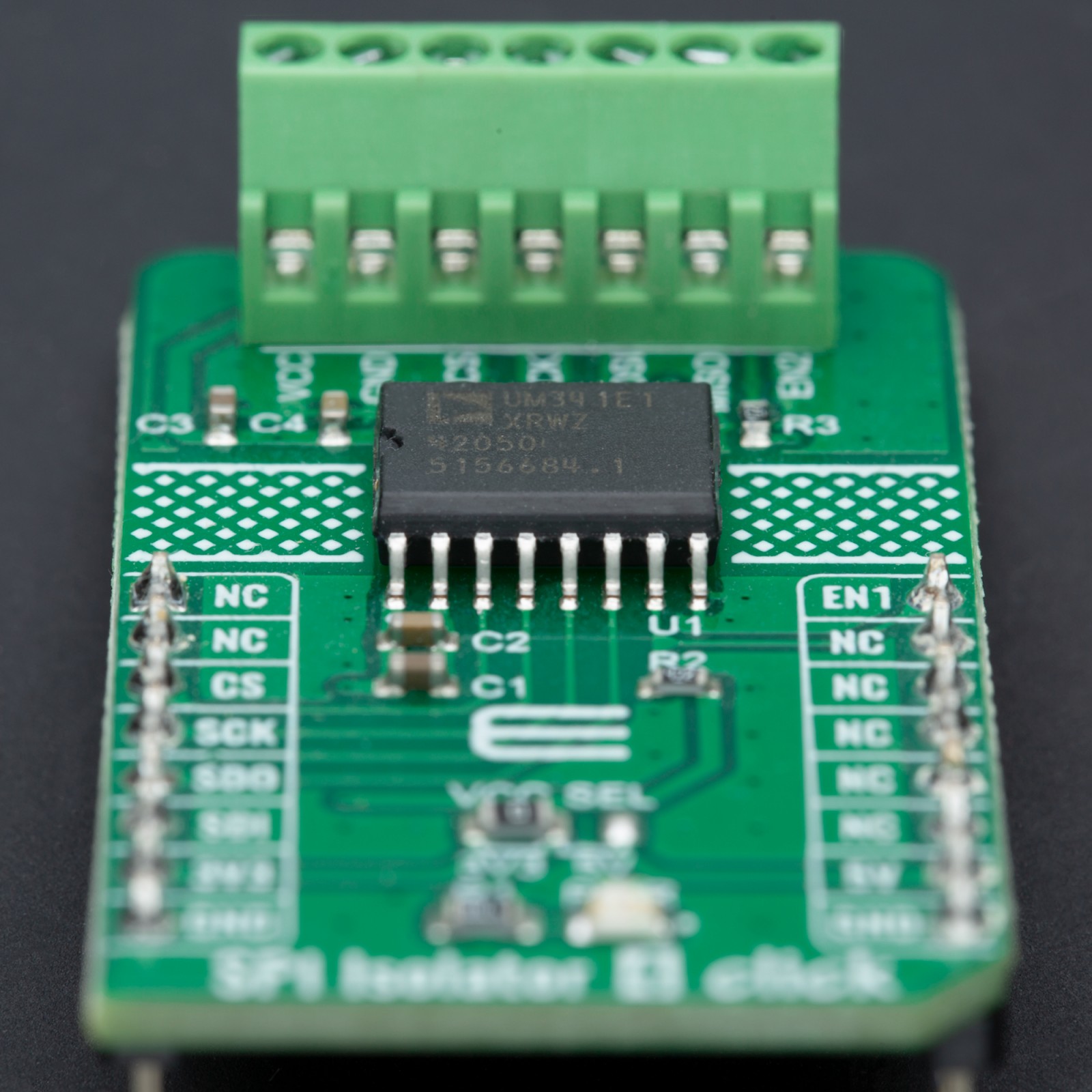
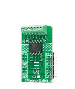
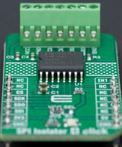
SPI Isolator 4 Click as its foundation uses the ADuM341E1BRWZ, a quad-channel digital isolator optimized for a serial peripheral interface from Analog Devices. This isolation component provides outstanding performance characteristics by combining high speed and CMOS technology and uses a high-frequency carrier to transmit data across the isolation barrier using iCoupler chip scale transformer coils separated by layers of polyimide isolation. Its data channels are independent and available in various configurations with a withstand voltage rating of 5kVrms.
Using an ON/OFF keying (OOK) technique and the differential architecture, the ADuM341E has a very low propagation delay and high speed. It operates with the external supply voltage ranging from 2.25V to 5.5V, providing compatibility with lower voltage systems enabling voltage translation functionality across the isolation barrier. The ADuM341E architecture is designed for high common-mode transient (CMTI) immunity and high immunity to electrical noise and magnetic interference.
Unlike other optocoupler alternatives, dc correctness is ensured in the absence of input logic transitions. Two different fail-safe options are available, by which the outputs go into a predetermined state when the input power supply is not applied, or the inputs are disabled.
SPI Isolator 4 Click communicates with an MCU using the SPI serial interface with a maximum data rate of 100Mbps. This Click board™ also comes with an SDO line enable control pin, labeled as EN1 routed on the PWM pin of the mikroBUS™ socket. When EN1 is in a high logic state, the SDO line is enabled, and when EN1 is in a low logic state, the SDO line is disabled to the high-Z state.
This Click board™ can operate with both 3.3V and 5V logic voltage levels selected via the VCC SEL jumper. This way, both 3.3V and 5V capable MCUs can use the SPI communication lines correctly. However, the Click board™ comes equipped with a library containing easy-to-use functions and an example code that can be used, as a reference, for further development.
Specifications
Type
Isolators,SPI
Applications
Can be used for general SPI-bus isolation, RS485 and CAN FG industrial field bus isolation, GPIO multichannel isolation, and many more
On-board modules
ADuM341E – quad-channel digital isolator optimized for a serial peripheral interface from Analog Devices
Key Features
High common-mode transient immunity, high performance, low propagation delay, 100Mbps maximum guaranteed data rate, safety and regulatory approvals, low power consumption, and more
Interface
SPI
Feature
No ClickID
Compatibility
mikroBUS™
Click board size
M (42.9 x 25.4 mm)
Input Voltage
3.3V or 5V,External
Pinout diagram
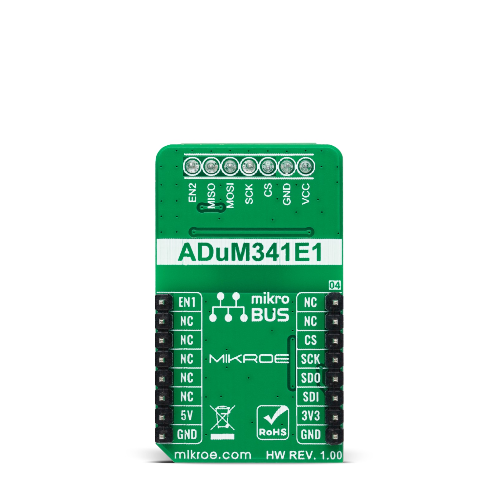
This table shows how the pinout on SPI Isolator 4 Click corresponds to the pinout on the mikroBUS™ socket (the latter shown in the two middle columns).
Onboard settings and indicators
Label | Name | Default | Description |
---|---|---|---|
LD1 | PWR | – | Power LED Indicator |
JP1 | VCC SEL | Left | Logic Level Voltage Selection 3V3/5V: Left position 3V3, Right position 5V |
SPI Isolator 4 Click electrical specifications
Description | Min | Typ | Max | Unit |
---|---|---|---|---|
Supply Voltage VCC | 3.3 | – | 5 | V |
External Supply Voltage | 3.3 | – | 5 | V |
Isolation Voltage | – | – | 5 | kVrms |
Data Rate | – | – | 100 | Mbps |
Software Support
We provide a library for the SPI Isolator 4 Click as well as a demo application (example), developed using Mikroe compilers. The demo can run on all the main Mikroe development boards.
Package can be downloaded/installed directly from NECTO Studio Package Manager(recommended), downloaded from our LibStock™ or found on Mikroe github account.
Library Description
This library contains API for SPI Isolator 4 Click driver.
Key functions
-
spiisolator4_generic_write
SPI Isolator 4 data writing function. -
spiisolator4_generic_read
SPI Isolator 4 data reading function. -
spiisolator4_set_enable
SPI Isolator 4 enable isolator function.
Example Description
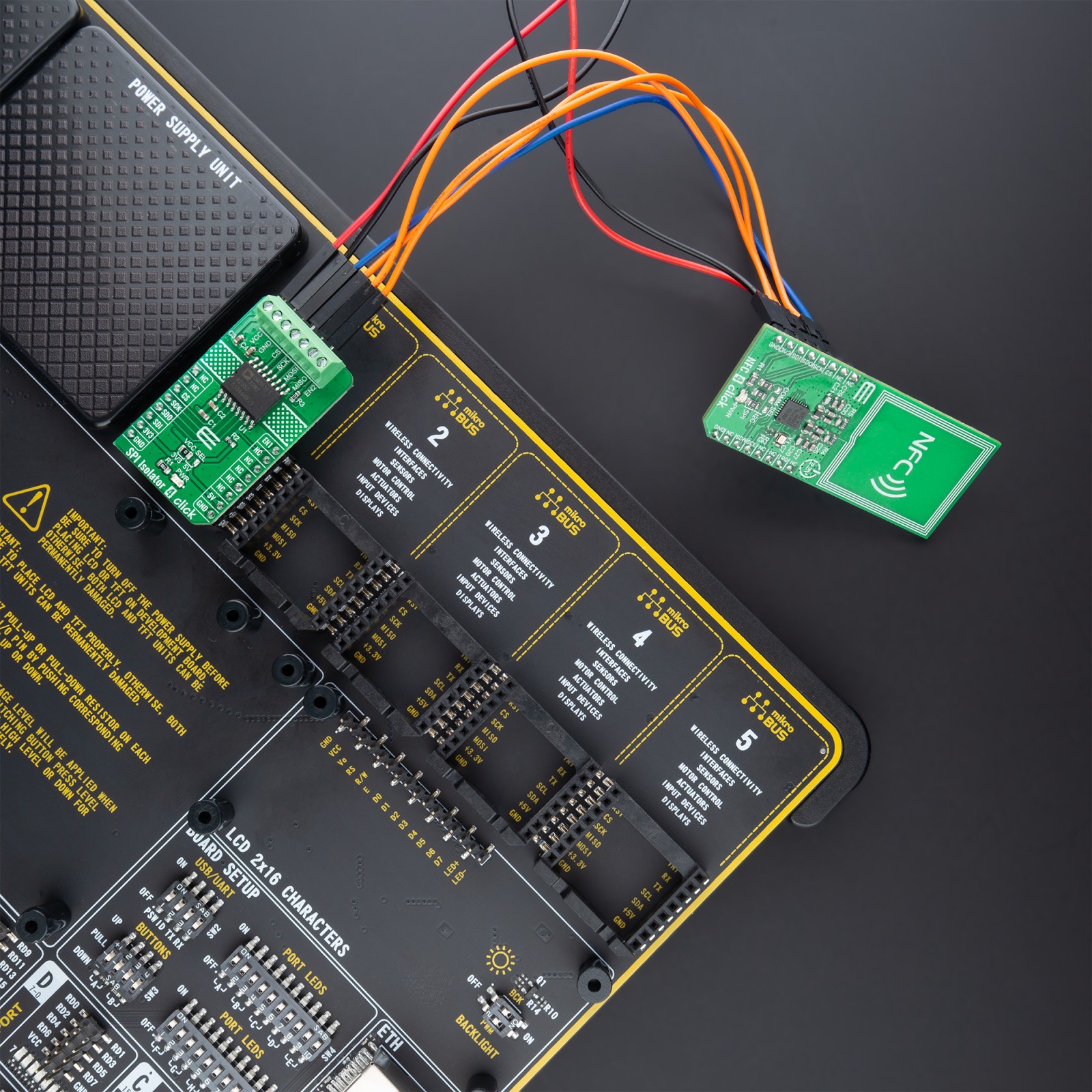
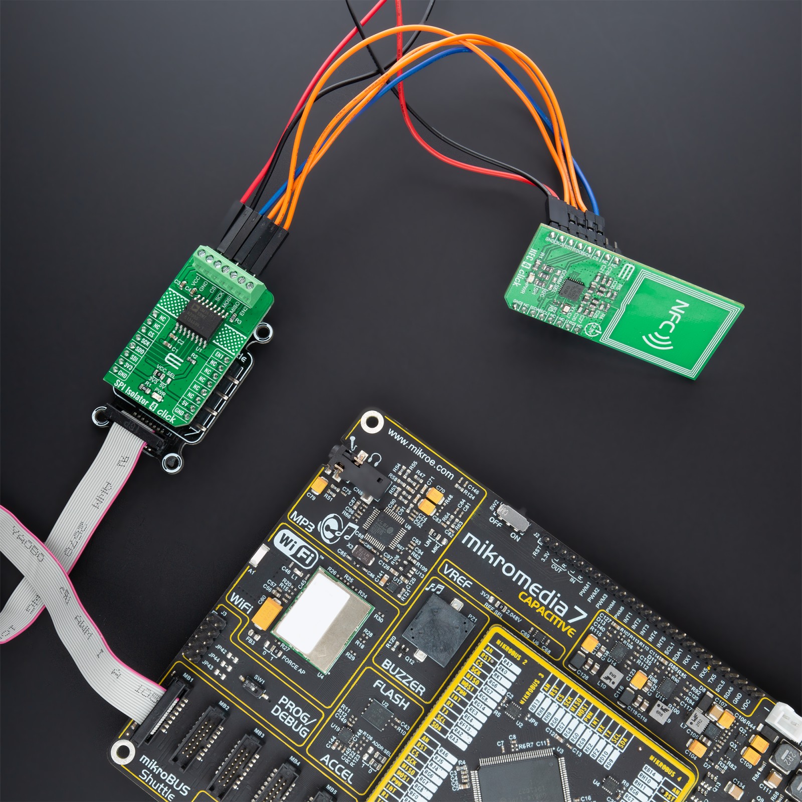
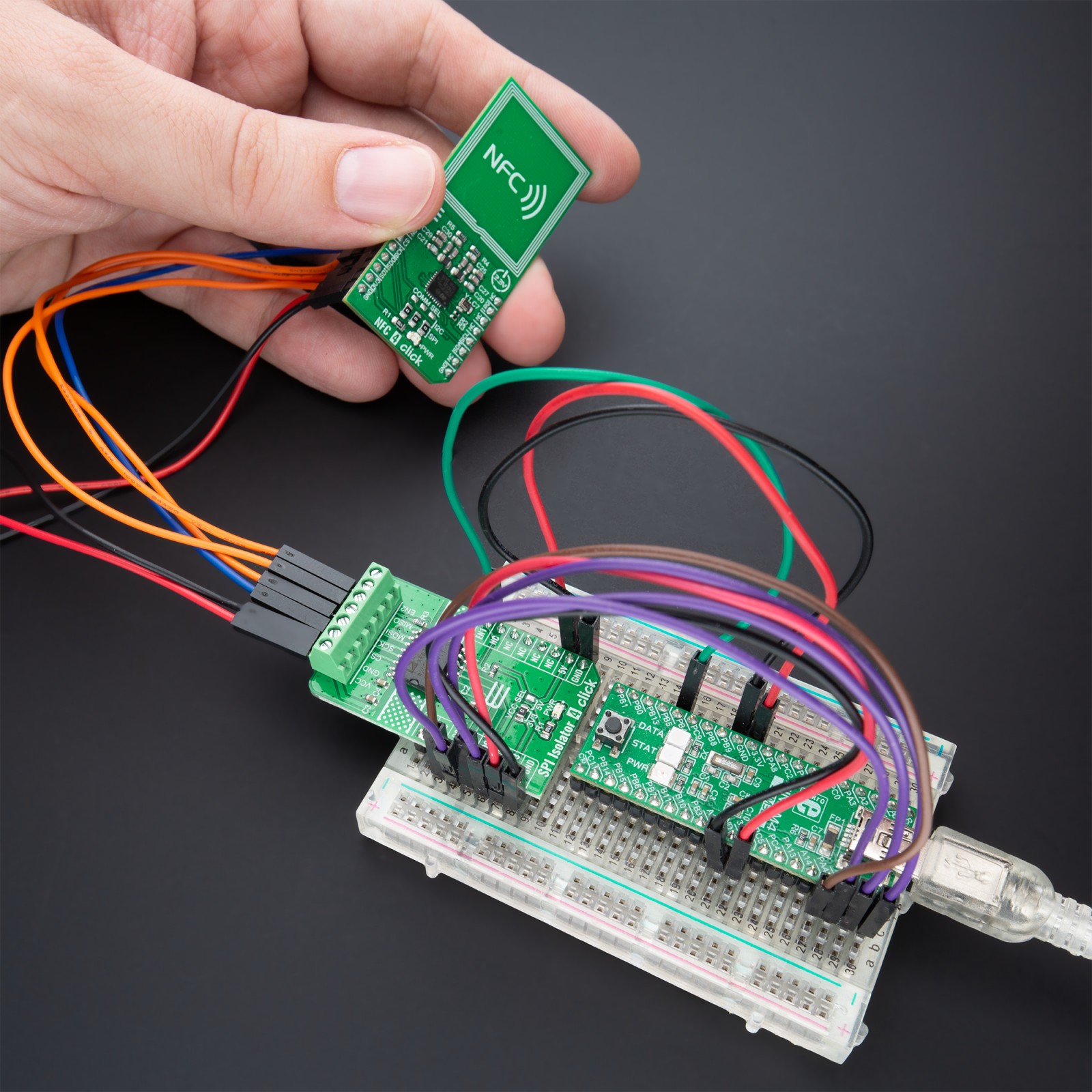
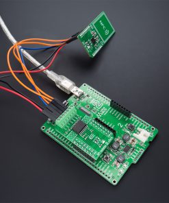
This library contains API for the SPI Isolator 4 click driver. This demo application shows an example of an SPI Isolator 4 click wired to the nvSRAM 4 click for reading Device ID.
void application_task ( void )
{
get_device_id( );
log_printf( &logger, " Device ID : 0x%.8LXrn", device_id );
log_printf( &logger, "--------------------------rn" );
Delay_ms( 1000 );
}
The full application code, and ready-to-use projects can be installed directly from NECTO Studio Package Manager (recommended), downloaded from our LibStock™ or found on Mikroe github account.
Other Mikroe Libraries used in the example:
- MikroSDK.Board
- MikroSDK.Log
- Click.SPIIsolator4
Additional notes and informations
Depending on the development board you are using, you may need USB UART click, USB UART 2 Click or RS232 Click to connect to your PC, for development systems with no UART to USB interface available on the board. UART terminal is available in all Mikroe compilers.
mikroSDK
This Click board™ is supported by a mikroSDK – Mikroe Software Development Kit. To ensure proper operation of mikroSDK compliant Click board™ demo applications, mikroSDK should be downloaded from LibStock and installed for the compiler you are using.
For more information about mikroSDK, visit the official page.