How does it work?
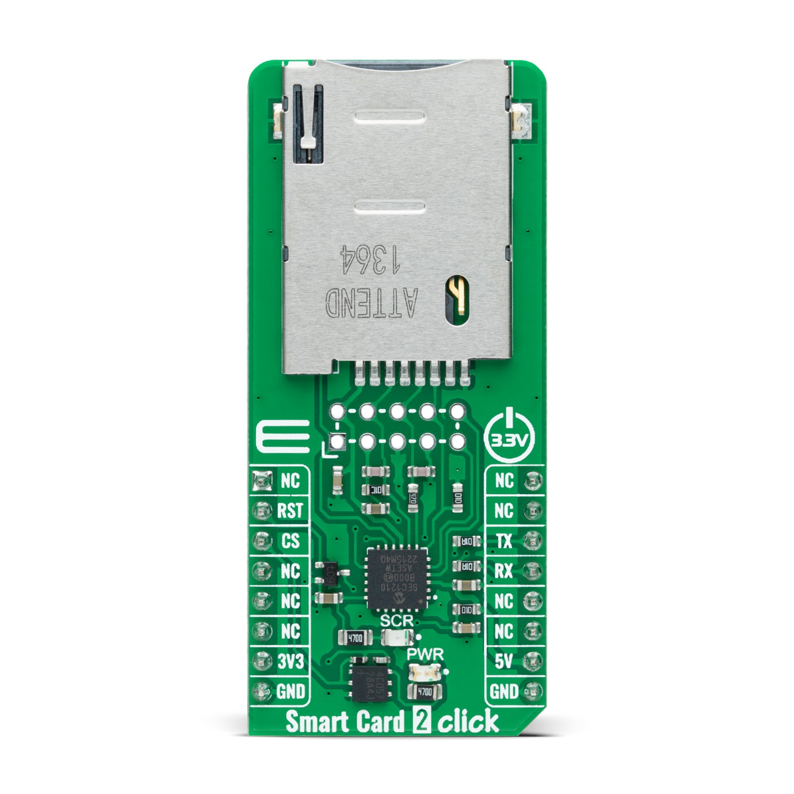
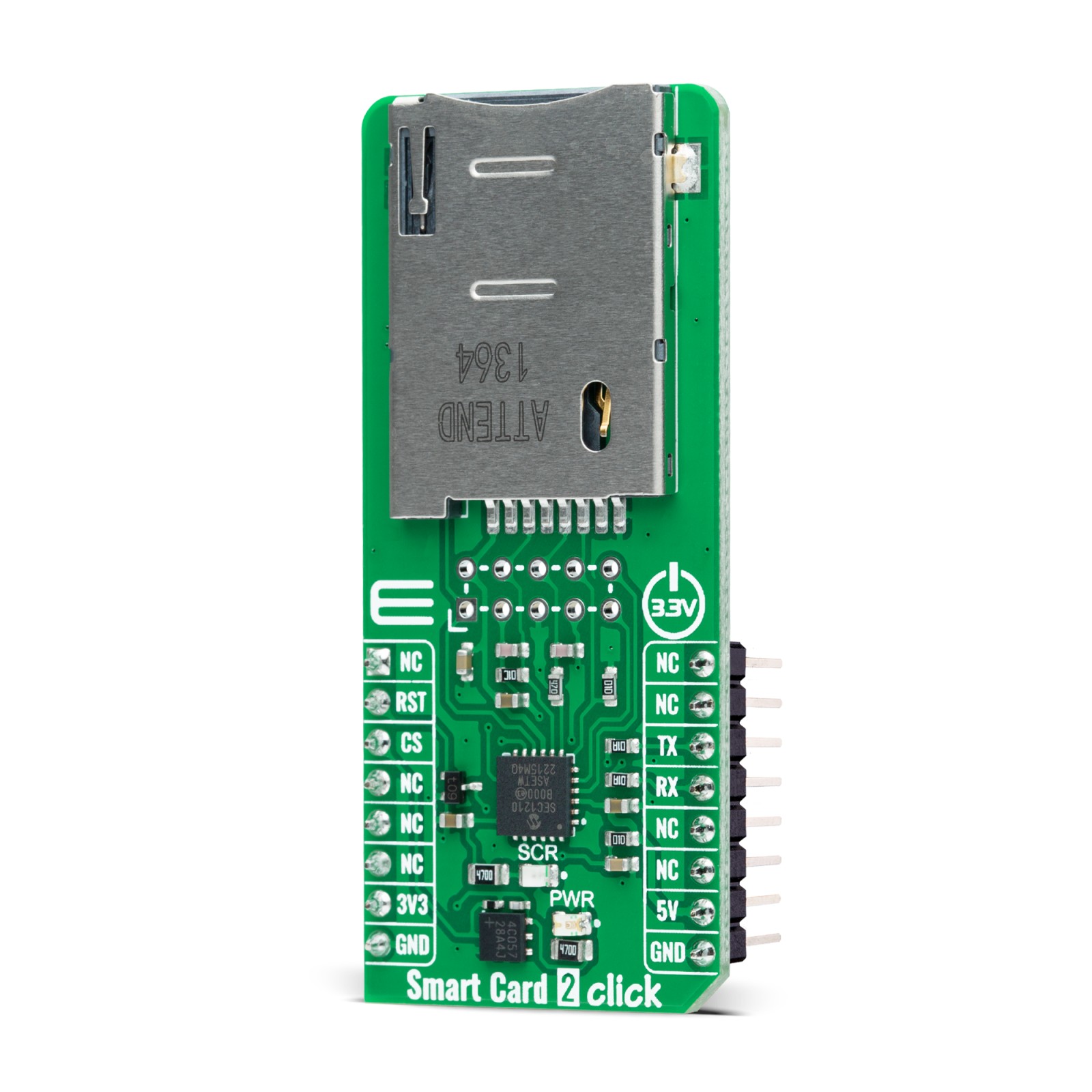
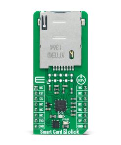
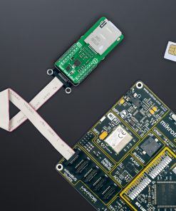
Smart Card 2 Click is based on the SEC1210, a high-performance single-chip Smart Card controller with a UART interface from Microchip. The SEC1210 is controlled by an enhanced integrated 8051 CPU, with all chip peripherals accessed and managed through the SFR or XDATA register space. Besides, it is fully compliant with the prevailing Smart Card standards (ISO7816, EMV, and PC/SC), keeps up with all requirements for communication bit rate, and includes support for proposed bit rates up to 826Kbps. The SEC1210 power unit is regulated and switched internally, supporting all 5V, 3V, and 1.8V Smart Cards (classes A, B, and C, respectively).
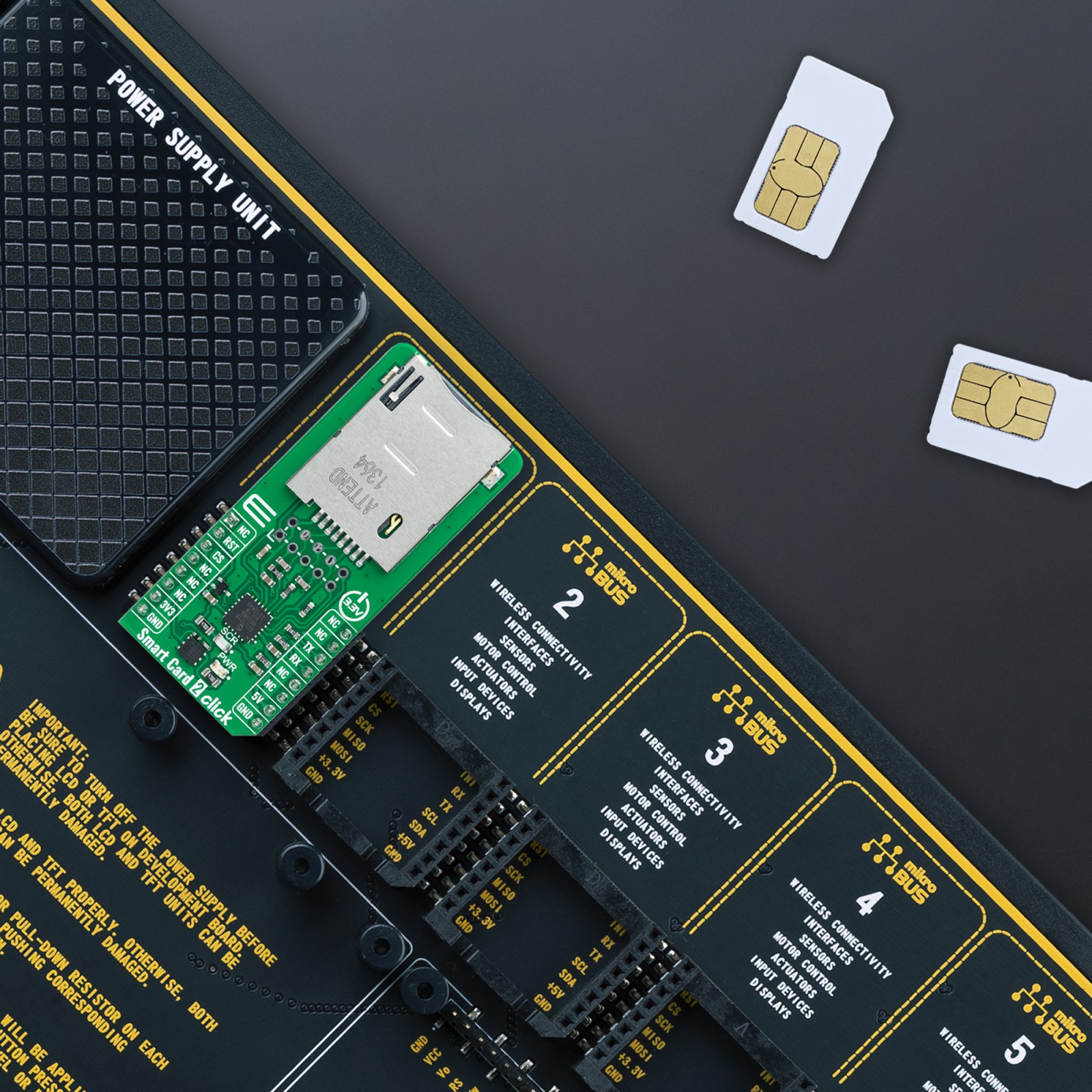
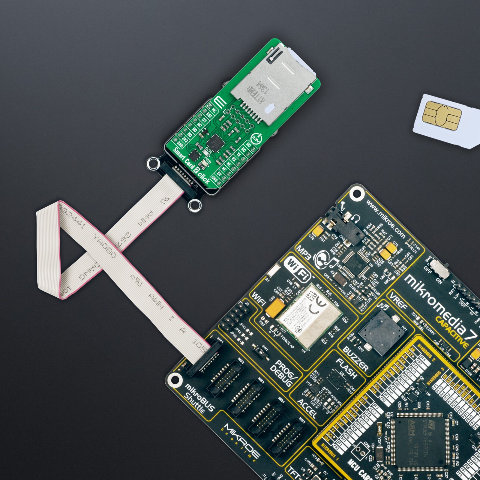
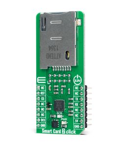
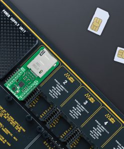
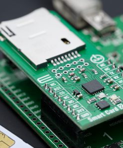
The SEC1210 utilizes TrustSpan™ technology that enables digital systems to communicate securely, process, move and store information. A populated onboard card holder supports data processing with 2FF smart cards. An additional connector for external connection also allows the processing of a standard 1FF card, making it ideal for electronic processes such as personal identification, access control (physical and logical access), authentication, and many more.
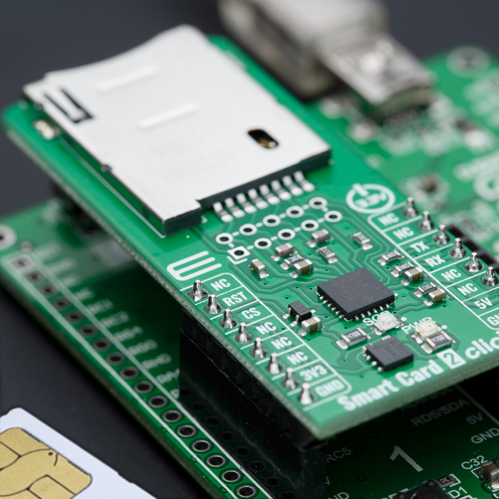
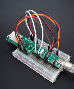
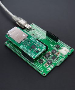
This Click board™ communicates with MCU using the UART interface with commonly used UART RX/TX and operates at 115200 bps by default configuration to transmit and exchange data with the host MCU. The sequence activation/deactivation process itself is possible through software. Still, hardware deactivation is also supported when a card is pulled out, whereby the required sequence is ensured regardless of software participation. In addition, Smart Card 2 Click also possesses a general Reset feature routed to the RST pin on the mikroBUS™ socket puts the module into a Reset state, while a yellow LED indicator labeled SRC represents a Smart Card status indicator. The blinking of this LED indicates that the Smart Card data processing is in progress.
This Click board™ can operate with both 3.3V and 5V MCUs, while SEC1210 uses only 5V from mikroBUS™ power rail as its primary power supply. However, the Click board™ comes equipped with a library containing functions and example code that can be used as a reference for further development.
Specifications
Type
Smart Card
Applications
Can be used for personal identification, access control (physical and logical access), authentication, and more
On-board modules
SEC1210 – single-chip Smart Card controller from Microchip
Key Features
High performance, low power consumption, fully compliant with Smart card standards, UART interface, external Smart Card connection, data processing LED indicator, and more
Interface
UART
Feature
ClickID
Compatibility
mikroBUS™
Click board size
L (57.15 x 25.4 mm)
Input Voltage
3.3V,5V
Pinout diagram
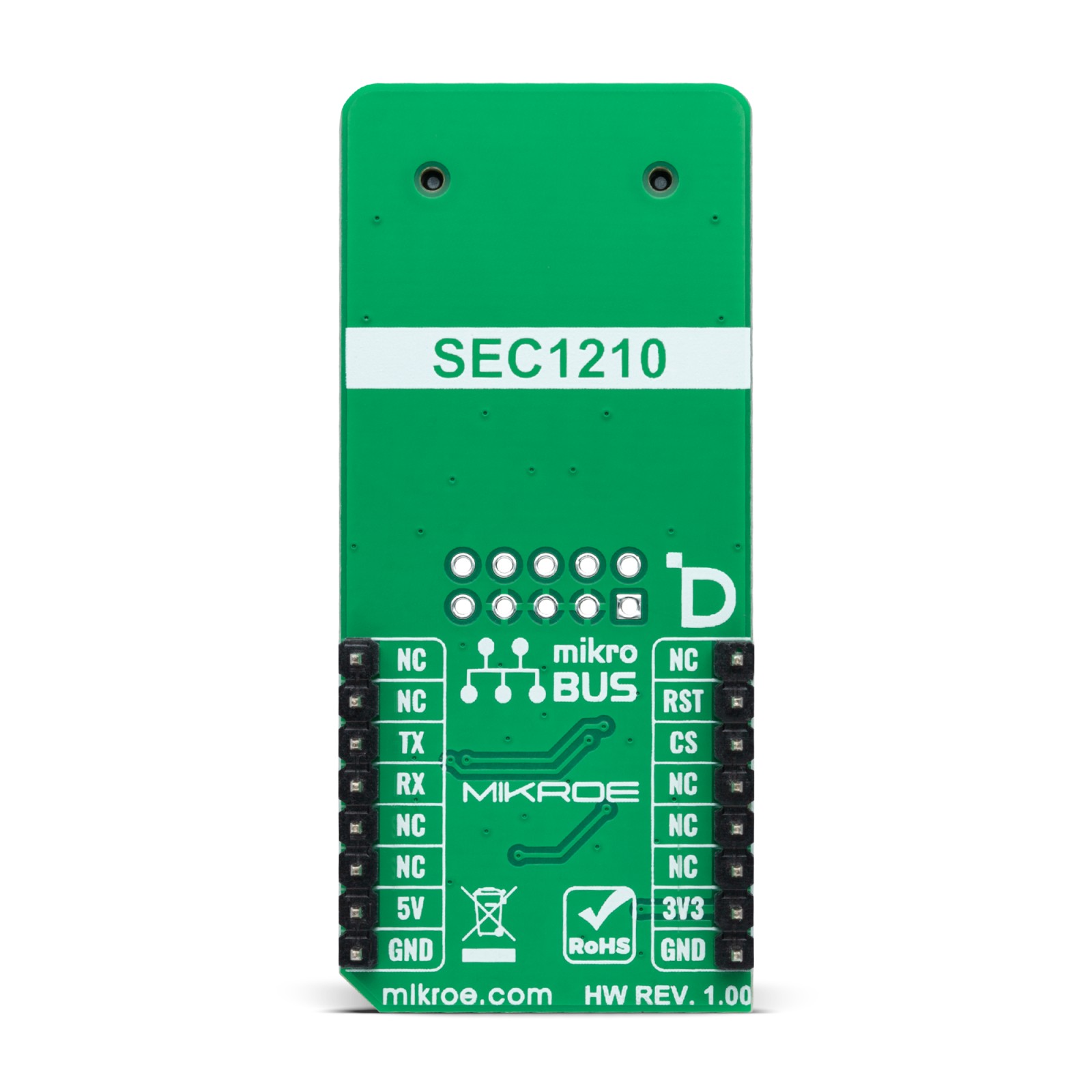
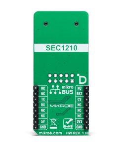
This table shows how the pinout on Smart Card 2 Click corresponds to the pinout on the mikroBUS™ socket (the latter shown in the two middle columns).
Onboard settings and indicators
Label | Name | Default | Description |
---|---|---|---|
LD1 | PWR | – | Power LED Indicator |
LD2 | SCR | – | Smart Card Status LED Indicator |
J1 | – | Unpopulated | External Smart card Connection Header |
Smart Card 2 Click electrical specifications
Description | Min | Typ | Max | Unit |
---|---|---|---|---|
Supply Voltage | 3.3 | – | 5 | V |
Software Support
We provide a library for the Smart Card 2 Click as well as a demo application (example), developed using Mikroe compilers. The demo can run on all the main Mikroe development boards.
Package can be downloaded/installed directly from NECTO Studio Package Manager(recommended), downloaded from our LibStock™ or found on Mikroe github account.
Library Description
This library contains API for Smart Card 2 Click driver.
Key functions
-
smartcard2_send_ccid
This function sends the CCID command message by using UART serial interface. -
smartcard2_read_ccid
This function reads a CCID response or event message by using UART serial interface. -
smartcard2_icc_power_on
This function activates the card by performing an ICC power ON command. The device will respond with a data block containing ICC ATR (Answer to Reset) message.
Example Description
This example demonstrates the use of Smart Card 2 Click board™ by checking the SIM card presence and activating the card on insert. The card should respond with an ATR (Answer to Reset) message.
void application_task ( void )
{
smartcard2_ccid_t ccid = { 0 };
if ( SMARTCARD2_OK == smartcard2_read_ccid ( &smartcard2, &ccid ) )
{
smartcard2_display_ccid_message ( ccid );
}
if ( SMARTCARD2_ICC_PRESENT == icc_status )
{
log_printf( &logger, " Activating card... rn" );
smartcard2_icc_power_on ( &smartcard2, SMARTCARD2_POWER_SEL_3V );
Delay_ms ( 100 );
}
}
The full application code, and ready to use projects can be installed directly from NECTO Studio Package Manager(recommended), downloaded from our LibStock™ or found on Mikroe github account.
Other Mikroe Libraries used in the example:
- MikroSDK.Board
- MikroSDK.Log
- Click.SmartCard2
Additional notes and informations
Depending on the development board you are using, you may need USB UART click, USB UART 2 Click or RS232 Click to connect to your PC, for development systems with no UART to USB interface available on the board. UART terminal is available in all Mikroe compilers.
mikroSDK
This Click board™ is supported with mikroSDK – Mikroe Software Development Kit. To ensure proper operation of mikroSDK compliant Click board™ demo applications, mikroSDK should be downloaded from the LibStock and installed for the compiler you are using.
For more information about mikroSDK, visit the official page.