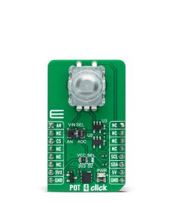

POT 4 Click
R410.00 ex. VAT
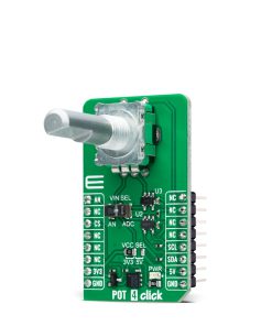
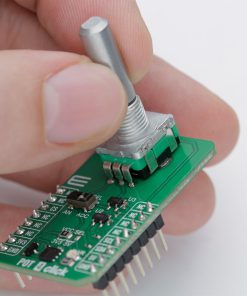
POT 4 Click is a compact add-on board with accurate selectable reference voltage output. This board features the PRS11R-425F-S103B1, a high-quality 11mm rotary 10k potentiometer from Bourns. The PRS11R-425F-S103B1 features a small form factor, offers an push-on momentary switch, a flatted shaft style, and a wide operating temperature range. It comes with a high-resolution 12-bit ADC, capable of detecting even the slightest movement while digitizing its position, alongside a rail-to-rail buffering operational amplifier, which provides constant input and output impedance. The user can process the output signal in analog or digital form. This Click board™ can be used in audio and lighting applications, laboratory equipment, industrial automation controls, and other applications where a reliable potentiometer is required.
POT 4 Click is fully compatible with the mikroBUS™ socket and can be used on any host system supporting the mikroBUS™ standard. It comes with the mikroSDK open-source libraries, offering unparalleled flexibility for evaluation and customization. What sets this Click board™ apart is the groundbreaking ClickID feature, enabling your host system to seamlessly and automatically detect and identify this add-on board.
Stock: Lead-time applicable.
| 5+ | R389.50 |
| 10+ | R369.00 |
| 15+ | R348.50 |
| 20+ | R335.38 |
How does it work?
POT 4 Click is based on the PRS11R-425F-S103B1, a high-quality rotary 10k potentiometer from Bourns providing very accurate voltage output. The PDB081-P10-103B1 features a small form factor, offers a push-on momentary switch, a flatted shaft style, and a wide operating temperature range, withstanding 50V maximum voltage. Typical applications include consumer white goods, test and measurement equipment, communications and laboratory equipment, and other applications requiring an analog or digitized control voltage.

The output of the potentiometer is brought to the non-inverting input of the OPA344, a rail-to-rail operational amplifier from Texas Instruments, used as a stable unity gain buffer, providing a constant input and output impedance. Without a buffer, the variable impedance would affect the reference voltage. Therefore, the OPA344 ensures good stability of the circuit.
A buffered signal can be converted to a digital value using the MCP3221, a successive approximation A/D converter with a 12-bit resolution from Microchip using a 2-wire I2C compatible interface, or can be sent directly to an analog pin of the mikroBUS™ socket labeled as AN. The selection can be performed by using an onboard SMD switch labeled as VIN SEL, placing it in an appropriate position marked as AN or ADC. Noting that the PRS11R-425F-S103B1 has an optional push momentary switch, this Click board™ also has an interrupt that will signal to users when this feature is used.
This Click board™ can operate with both 3.3V and 5V logic voltage levels selected via the VCC SEL jumper. This way, both 3.3V and 5V capable MCUs can use the communication lines properly. The Click board™ comes equipped with a library containing easy-to-use functions and an example code that can be used, as a reference, for further development.
Specifications
Type
Potentiometer
Applications
Can be used in audio and lighting applications, laboratory equipment, industrial automation controls, and other applications where a reliable potentiometer is required
On-board modules
PRS11R-425F-S103B1 – high-quality rotary 10k potentiometer from Bourns
Key Features
Resistance up to 10k, flatted metal shaft, low profile, push momentary switch, wide temperature and voltage range, wide mechanical angle, long rotational life, selectable analog or digital output, and more
Interface
Analog,I2C
Feature
ClickID
Compatibility
mikroBUS™
Click board size
M (42.9 x 25.4 mm)
Input Voltage
3.3V or 5V
Pinout diagram
This table shows how the pinout on POT 4 Click corresponds to the pinout on the mikroBUS™ socket (the latter shown in the two middle columns).
| Notes | Pin | Pin | Notes | ||||
|---|---|---|---|---|---|---|---|
| Analog Signal | AN | 1 | AN | PWM | 16 | NC | |
| NC | 2 | RST | INT | 15 | SW | Switch Interrupt | |
| ID COMM | CS | 3 | CS | RX | 14 | NC | |
| NC | 4 | SCK | TX | 13 | NC | ||
| NC | 5 | MISO | SCL | 12 | SCL | I2C Clock | |
| NC | 6 | MOSI | SDA | 11 | SDA | I2C Data | |
| Power Supply | 3.3V | 7 | 3.3V | 5V | 10 | 5V | Power Supply |
| Ground | GND | 8 | GND | GND | 9 | GND | Ground |
Onboard settings and indicators
| Label | Name | Default | Description |
|---|---|---|---|
| LD1 | PWR | – | Power LED Indicator |
| JP1 | VCC SEL | Left | Logic Level Voltage Selection 3V3/5V: Left position 3V3, Right position 5V |
| SW1 | VIN SEL | Right | Output Signal A/D Selection AN/ADC: Left position AN, Right position ADC |
POT 4 Click electrical specifications
| Description | Min | Typ | Max | Unit |
|---|---|---|---|---|
| Supply Voltage | 3.3 | – | 5 | V |
| ADC Resolution | – | 12 | – | bit |
| Potentiometer Resistance | – | – | 10 | kΩ |
Software Support
We provide a library for the POT 4 Click as well as a demo application (example), developed using Mikroe compilers. The demo can run on all the main Mikroe development boards.
Package can be downloaded/installed directly from NECTO Studio Package Manager (recommended), downloaded from our LibStock™ or found on Mikroe github account.
Library Description
This library contains API for POT 4 Click driver.
Key functions
-
pot4_get_switch_pinThis function returns the switch (SW) pin logic state. -
pot4_read_voltageThis function reads raw ADC value and converts it to proportional voltage level. -
pot4_convert_voltage_to_percentsThis function converts analog voltage to potentiometer position in percents.
Example Description
This example demonstrates the use of POT 4 Click board™ by reading and displaying the potentiometer position.
 void application_task ( void )
 {
     if ( !pot4_get_switch_pin ( &pot4 ) )
     {
         float voltage = 0;
         if ( POT4_OK == pot4_read_voltage ( &pot4, &voltage ) )
         {
             log_printf( &logger, " AN Voltage : %.3f Vrn", voltage );
             log_printf( &logger, " Potentiometer : %u %%rnn",
                         ( uint16_t ) pot4_convert_voltage_to_percents ( &pot4, voltage ) );
             Delay_ms( 1000 );
         }
     }
 }
The full application code, and ready to use projects can be installed directly from NECTO Studio Package Manager (recommended), downloaded from our LibStock™ or found on Mikroe github account.
Other Mikroe Libraries used in the example:
- MikroSDK.Board
- MikroSDK.Log
- Click.POT4
Additional notes and informations
Depending on the development board you are using, you may need USB UART click, USB UART 2 Click or RS232 Click to connect to your PC, if no UART to USB interface is available on the development board. A UART terminal is available in all Mikroe compilers.
mikroSDK
This Click board™ is supported with mikroSDK – Mikroe Software Development Kit. To ensure proper operation of mikroSDK compliant Click board™ demo applications, mikroSDK should be downloaded from the LibStock and installed for the compiler you are using.
For more information about mikroSDK, visit the official page.
Resources
Downloads
| Weight | 22 g |
|---|---|
| Brand | MikroElektronika |