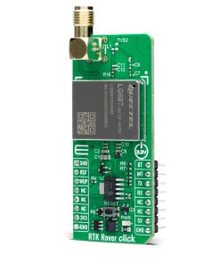
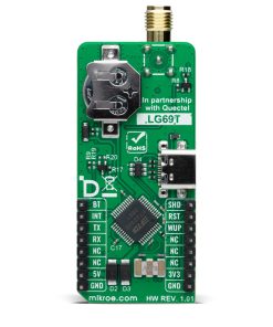
NOTE: The LG69TAMMD supports RTK functionality as a Rover, using the Base Station correction data to achieve centimeter precise positioning. To complement your RTK Rover Click with its compatible RTK Base Station, visit the RTK Base Station Click product page.
How does it work?
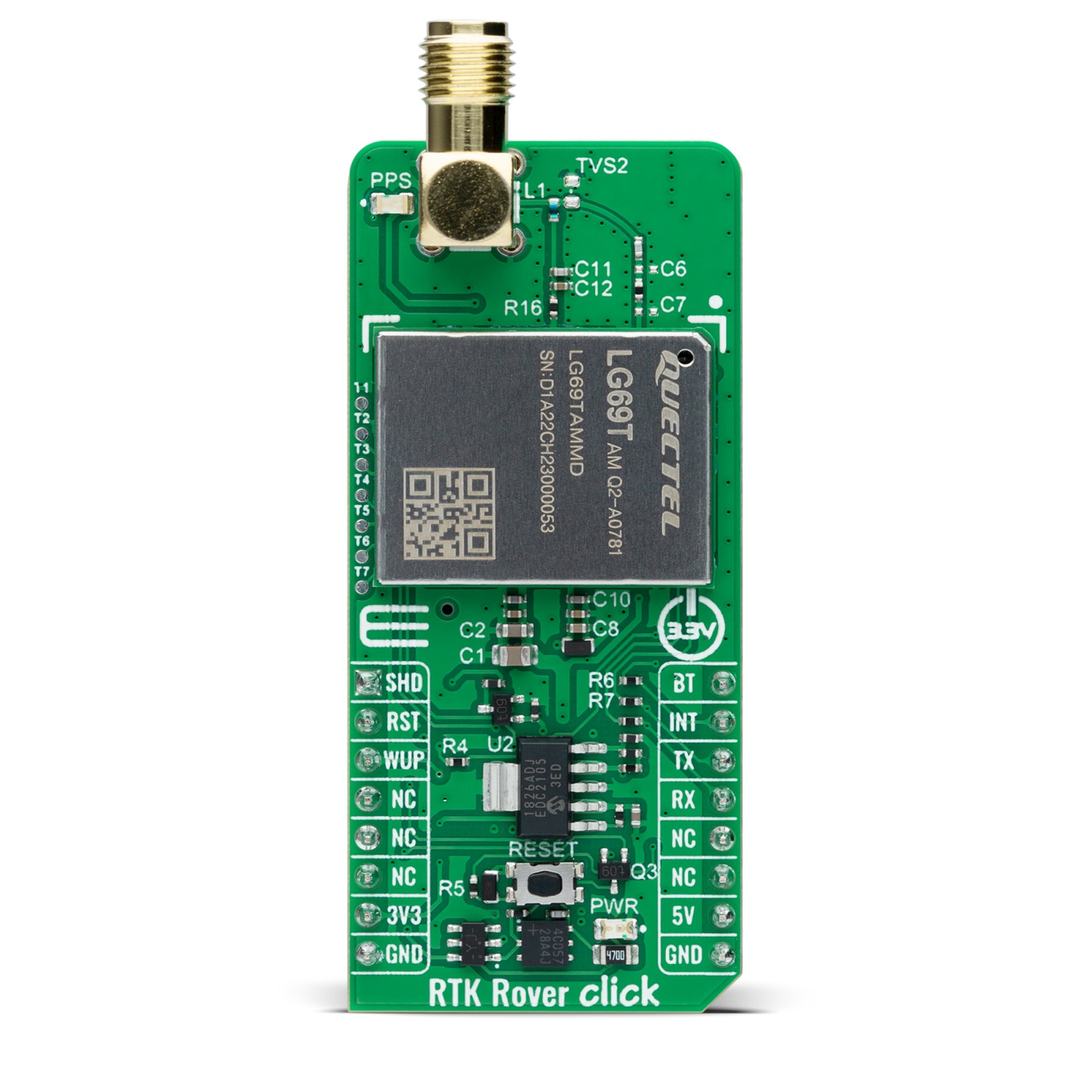
RTK Rover Click is based on the LG69TAMMD, a multi-constellation GNSS module featuring a high-performance and high-reliability positioning engine from Quectel Wireless Solutions, that facilitates a fast and precise GNSS positioning capability. The LG69TAMMD has a dual-band supporting up to three concurrent global constellations featuring STMicroelectronics®’ fifth generation positioning receiver platform with 80 tracking and four fast acquisition channels. It is characterized by a horizontal position accuracy of 1m autonomous (24h static) and 0.01m+1ppm RTK with a high performance YB0017AA mobile antenna in an open-sky environment and within 1km of the base station.
The primary function of the LG69TAMMD is PVT (RTK) which stands for Position, Velocity, and Time. Designed according to the IATF 16949:2016 standard, the LG69TAMMD comes with GPS+BDS+Galileo as a default GNSS constellation and an integrated LNA for improved sensitivity. It can receive and track GPS L1 C/A and L5 and Galileo E1 and E5a signals centered at 1575.42MHz and 1176.45MHz, and BeiDou B1I and B2a signals centered at 1561.098MHz and 1176.45MHz. The ability to receive and track BeiDou signals in conjunction with GPS results in higher coverage, improved reliability, and better accuracy.
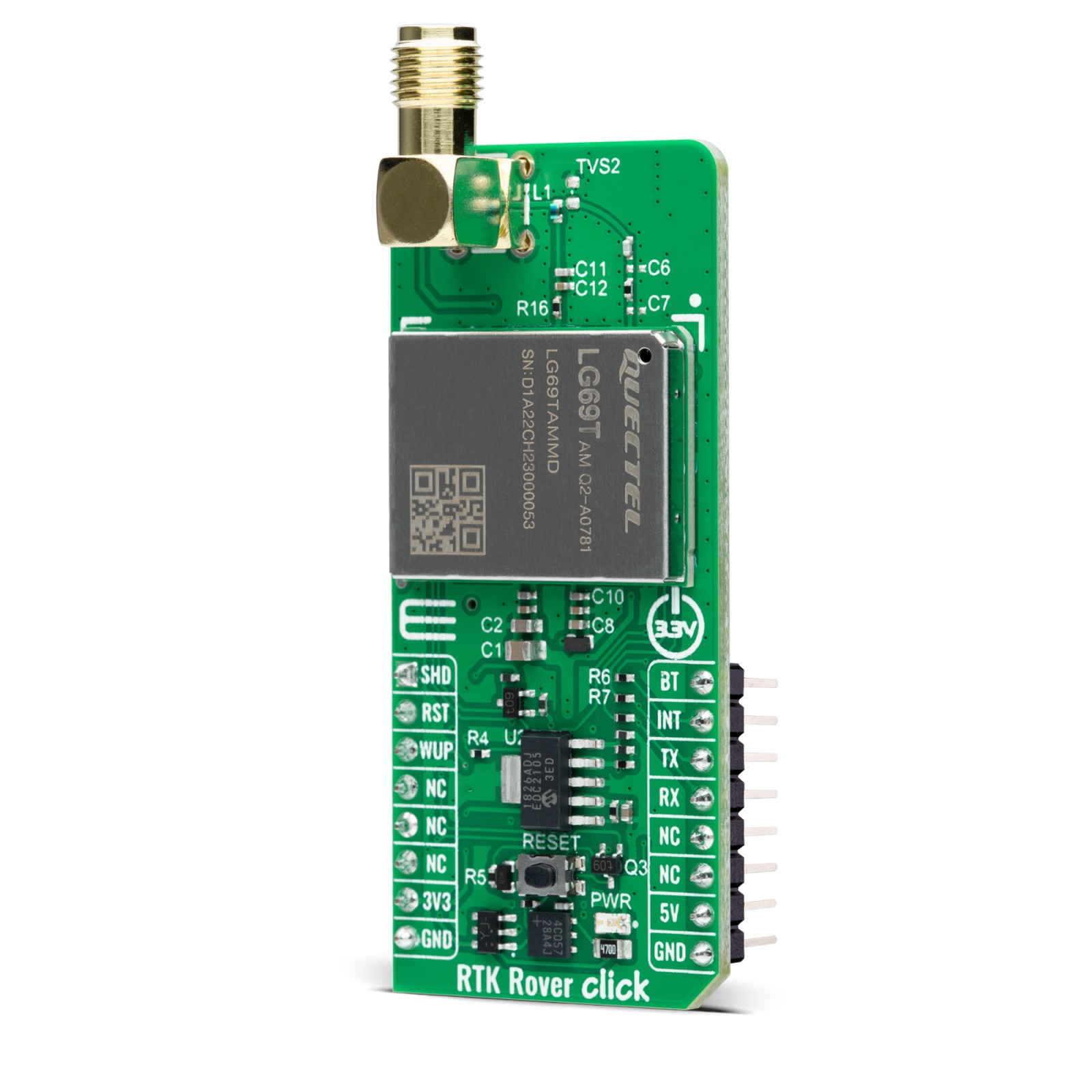
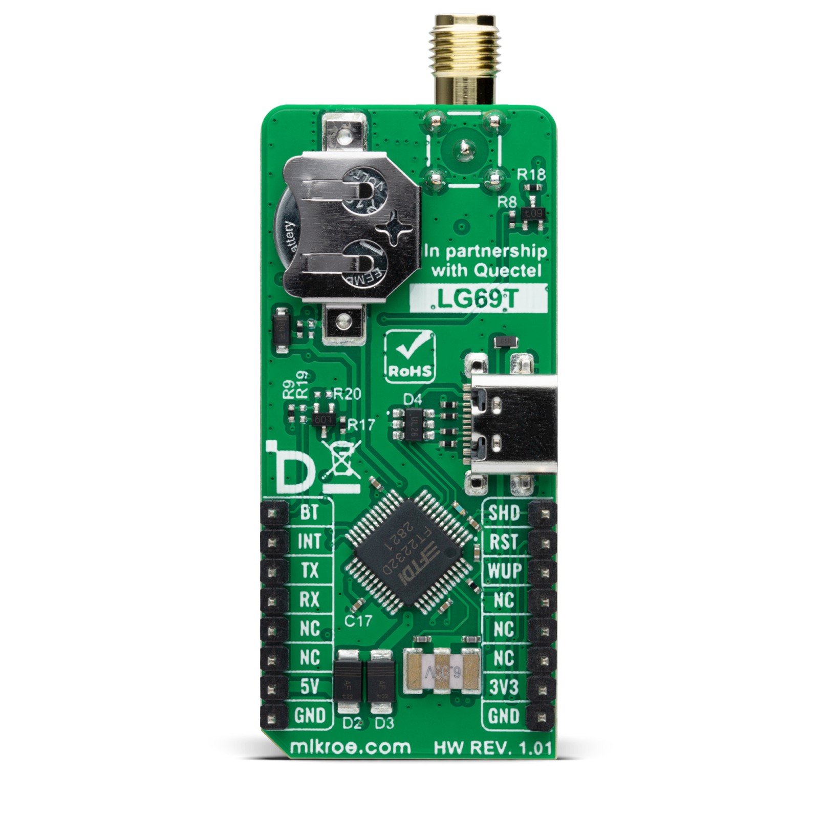
RTK Rover Click communicates with an MCU using the UART interface, with commonly-used RX and TX pins alongside one data-ready pin (INT), which informs the host MCU to receive data when the buffer transmission is full. It is also equipped with a USB type C connector, which allows the module to be powered and configured by a personal computer (PC) using FT2232D, a compact USB to a serial UART interface device designed to operate efficiently with USB host controllers.
Before supporting the RTK navigation technique, this module must receive the RTK correction messages via its UART port. In a default configuration, it will attempt to achieve the best positioning accuracy based on the correction data it receives. When the module receives an input stream of RTCM messages, it will enter RTK float mode, and once it fixes carrier phase ambiguities, it enters RTK fixed mode. It will typically take less than 60 seconds before the Rover can solve the carrier ambiguities and go from RTK float to RTK fixed mode.
In addition to the interface pins, this board uses a few additional mikroBUS™ pins. An active-low reset signal alongside an onboard RESET button, routed on the RST pin of the mikroBUS™ socket, performs a reset function of the module, WUP pin performs module wake-up, and the SHD pin routed on the AN pin of the mikroBUS™ socket offers a switch operation to turn ON/OFF the power supply to the LG69TAMMD. The module can use Boot Download Mode for firmware update via the BT pin routed on the RST pin of the mikroBUS™ socket, alongside a blue LED indicator marked as PPS for time pulse signal information and indication. The module enters Normal operating mode by keeping the BT pin on a low logic state during the Startup sequence. Otherwise, the module enters Boot Download Mode when the pin is high during Startup.
A specific addition to this Click board™ is several testpoints that enable the use of additional module features such as RTK positioning status indicator, Wheel tick pulse signal sampled from the wheel revolution sensors, or correction UART by default or NMEA output/raw data output.
This Click board™ can operate with both 3.3V and 5V MCUs. As its main power supply, the LG69TAMMD uses 3.3V obtained from the MCP1826 LDO but also has the possibility of using an additional backup power supply in the form of a coin-shaped battery. The board must perform appropriate logic voltage level conversion before using MCUs with different logic levels. However, the Click board™ comes equipped with a library containing functions and an example code that can be used as a reference for further development.
RTK Technology
The Global Navigation Satellite System (GNSS) is a widely deployed and accepted means of determining precise locations without the need for the coverage or signal strength of cellular networks. GNSS combined with RTK is a solution that can realize precise real-time positioning, with positional down to the centimeter level. Quectel’s ultra-compact, low-power GNSS modules, such as LG69T-AS and LG69T-AM, provided in the form of RTK Click boards™, cover the full range of requirements for high precision, dead reckoning and timing for applications as diverse as ADAS and self-driving, crewless flight, and smart agriculture.
In addition to the software support that Mikroe provides for this Click board™ in the form of libraries, functions, or example code, there is also software support provided by Quectel. Quectel’s QGNSS evaluation software equips end users with an easy way to interface to Quectel GNSS modules or boards, enabling easy evaluation, testing, development and debugging of GNSS.
For all additional support questions, the customers can submit a ticket to our Technical Support or Design Service Department page.
Specifications
Type
GPS/GNSS,Mesh Network,RTK
Applications
Can be used for PVT (Position, Velocity, and Time) applications such as drones, delivery robots, precision agriculture, mining/marine management, and automotive telematics
On-board modules
LG69TAMMD – multi-constellation GNSS module from Quectel Wireless Solutions
Key Features
Dual band, centimeter-level accuracy, 80 tracking channels and 4 fast acquisition channels, high-performance, high-reliability, supports up to 3 concurrent global constellations (GPS/QZSS, Galileo, and BDS), NMEA 0183/RTCM 3.x protocol, UART and USB interface, PPS indicator, and more
Interface
UART,USB
Feature
ClickID
Compatibility
mikroBUS™
Click board size
L (57.15 x 25.4 mm)
Input Voltage
3.3V,5V
Pinout diagram
This table shows how the pinout on RTK Rover Click corresponds to the pinout on the mikroBUS™ socket (the latter shown in the two middle columns).
Onboard settings and indicators
Label | Name | Default | Description |
---|---|---|---|
LD1 | PWR | – | Power LED Indicator |
LD2 | PPS | – | Time Pulse LED Indicatorr |
T1 | RESET | – | Reset Button |
RTK Rover Click electrical specifications
Description | Min | Typ | Max | Unit |
---|---|---|---|---|
Supply Voltage | 3.3 | – | 5 | V |
Operating Frequency | 1176.45 | – | 1575.42 | MHz |
Horizontal Position Accuracy | – | 1 | – | cm |
Software Support
We provide a library for the RTK Rover Click as well as a demo application (example), developed using Mikroe compilers. The demo can run on all the main Mikroe development boards.
Package can be downloaded/installed directly from NECTO Studio Package Manager(recommended), downloaded from our LibStock™ or found on Mikroe github account.
Library Description
This library contains API for RTK Rover Click driver.
Key functions
-
rtkrover_generic_read
This function reads a desired number of data bytes by using UART serial interface. -
rtkrover_clear_ring_buffers
This function clears UART tx and rx ring buffers. -
rtkrover_parse_gngga
This function parses the GNGGA data from the read response buffer.
Example Description
This example demonstrates the use of RTK Rover Click boards™ by reading and displaying the GPS coordinates.
void application_task ( void )
{
if ( RTKROVER_OK == rtkrover_process( &rtkrover ) )
{
if ( PROCESS_BUFFER_SIZE == app_buf_len )
{
rtkrover_parser_application( &rtkrover, app_buf );
}
}
}
The full application code, and ready to use projects can be installed directly from NECTO Studio Package Manager(recommended), downloaded from our LibStock™ or found on Mikroe github account.
Other Mikroe Libraries used in the example:
- MikroSDK.Board
- MikroSDK.Log
- Click.RTKRover
Additional notes and informations
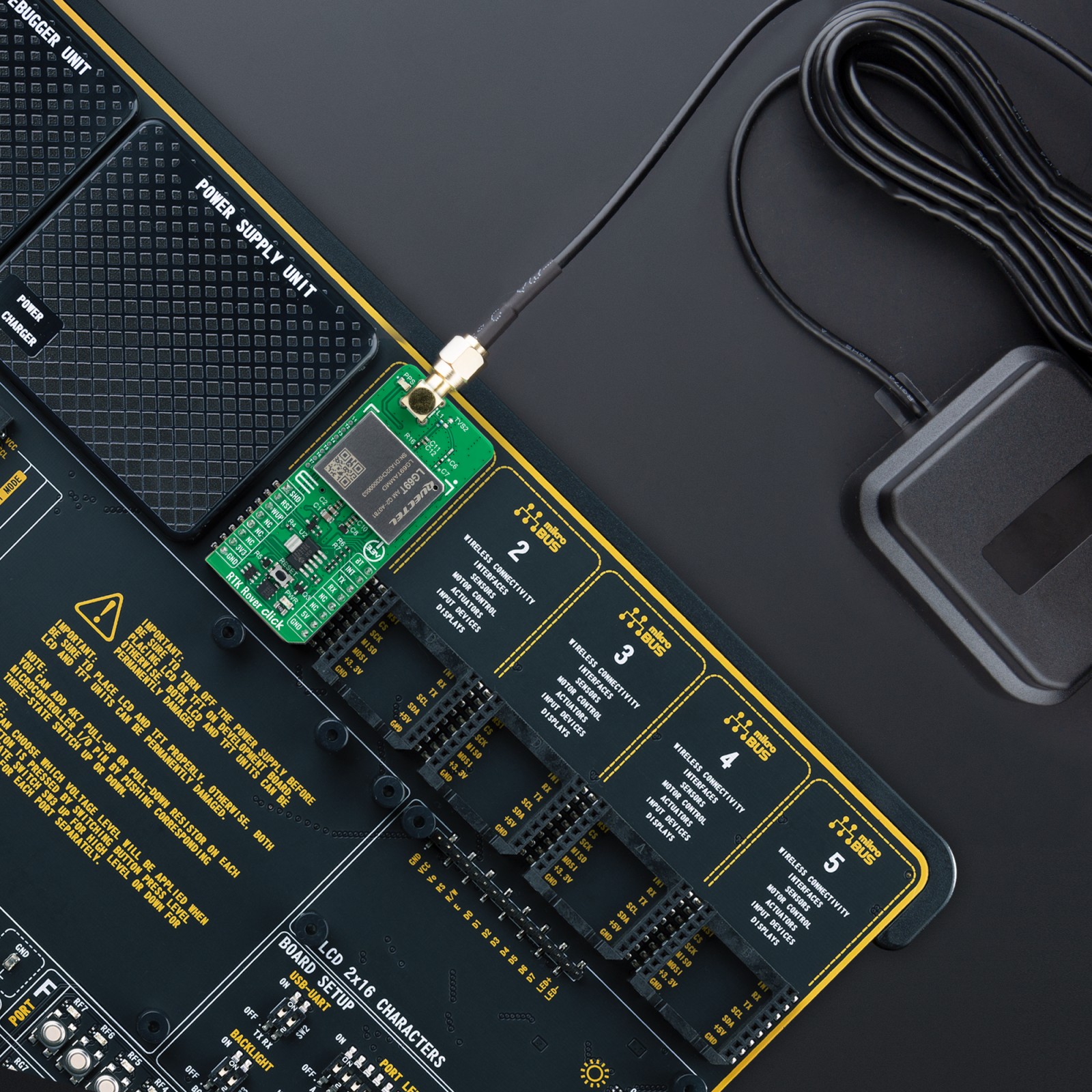
Depending on the development board you are using, you may need USB UART click, USB UART 2 Click or RS232 Click to connect to your PC, for development systems with no UART to USB interface available on the board. UART terminal is available in all Mikroe compilers.
mikroSDK
This Click board™ is supported with mikroSDK – MikroElektronika’s Software Development Kit. mikroSDK should be downloaded from the LibStock™ and installed for the compiler you are using to ensure proper operation of mikroSDK compliant Click board™ demo application.
For more information about mikroSDK, visit the official page.