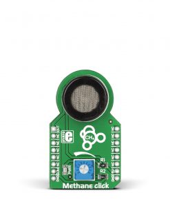
Color 16 Click
R720.00 ex. VAT
Color 16 Click is a compact add-on board providing an accurate color-sensing solution. This board features ams OSRAM’s AS7343, a 14-channel multi-purpose spectral sensor offering spectral response through a compatible I2C interface. It has a built-in aperture that controls the light entering the sensor array to increase accuracy, alongside precise optical filters integrated into standard CMOS silicon via deposited interference filter technology. The spectral response is defined by individual channels covering approximately 380nm to 1000nm with 11 channels centered in the visible spectrum, one near-infrared, and a clear channel. This Click board™ is suitable for reflective, transmissive, and emissive light applications.
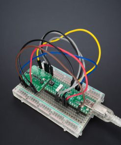
Color 16 Click is fully compatible with the mikroBUS™ socket and can be used on any host system supporting the mikroBUS™ standard. It comes with the mikroSDK open-source libraries, offering unparalleled flexibility for evaluation and customization. What sets this Click board™ apart is the groundbreaking ClickID feature, enabling your host system to seamlessly and automatically detect and identify this add-on board.
Stock: Lead-time applicable.
| 5+ | R684.00 |
| 10+ | R648.00 |
| 15+ | R612.00 |
| 20+ | R588.96 |
How does it work?
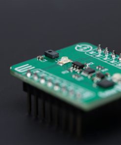
Color 16 Click is based on the AS7343, a 14-channel multi-purpose spectral sensor from ams OSRAM, providing fast and accurate spectral measurements. It is optimized for reflective (thanks to an onboard LDC red LED controlled through LDR pin), transmissive, and emissive light applications, including color matching, fluid or reagent analysis, lateral flow test applications, and spectral identification in the visible range. The AS7343 has a built-in aperture that controls the light entering the sensor array to increase accuracy. The spectral response is defined by individual channels covering approximately 380nm to 1000nm with 11 channels centered in the visible spectrum, one near-infrared, and a clear channel.

The AS7343 features a 5×5 photodiode array. Above and below the array there are two photodiodes with dedicated functions such as flicker detection and near-infrared response, while in each corner, the array has a photodiode without filter that is responsive in the visible spectral range. The AS7343 can detect 14 channels – 12 wavelengths, plus a clear and flicker output channel – making this Click board™ great for LED color calibration, miniature optical spectrometers, and more.
This sensor does not need a specific Power-Up sequence but requires a voltage of 1.8V for its interface and logic part to work correctly. Therefore, a small regulating LDO, the TLV700, provides a 1.8V out of selected mikroBUS™ power rail.
Color 16 Click communicates with MCU using the standard I2C 2-Wire interface with a maximum clock frequency of 400kHz, fully adjustable through software registers. Since the sensor for operation requires a power supply of 1.8V, this Click board™ also features the TXS0104E voltage-level translator. The communication lines are routed to the voltage-level translator allowing this Click board™ to work with any MCU properly. Also, it uses an interrupt pin, the INT pin of the mikroBUS™ socket, used when an interrupt occurs to alert the system when the color result crosses upper or lower threshold settings, and IO1 which is general-purpose input/output pin used as synchronization input to start/stop the spectral measurement.
This Click board™ can operate with either 3.3V or 5V logic voltage levels selected via the VCC SEL jumper. This way, both 3.3V and 5V capable MCUs can use the communication lines properly. Also, this Click board™ comes equipped with a library containing easy-to-use functions and an example code that can be used as a reference for further development.
Specifications
Type
Color Sensing,Optical
Applications
Ideal for reflective, transmissive, and emissive light applications
On-board modules
AS7343 – multi-purpose spectral sensor from ams OSRAM
Key Features
14 optical channels distributed over visible spectrum, near-infrared, and clear channel, dedicated functions such as flicker detection, high senistivity, fast measurements, low power consumption, interrupt, and more
Interface
I2C
Feature
ClickID
Compatibility
mikroBUS™
Click board size
S (28.6 x 25.4 mm)
Input Voltage
3.3V or 5V
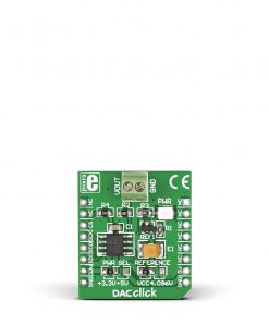
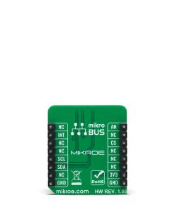
Pinout diagram
This table shows how the pinout on Color 16 Click corresponds to the pinout on the mikroBUS™ socket (the latter shown in the two middle columns).
| Notes | Pin | Pin | Notes | ||||
|---|---|---|---|---|---|---|---|
| NC | 1 | AN | PWM | 16 | IO1 | General-Purpose I/O | |
| Light Source Control | LDR | 2 | RST | INT | 15 | INT | Interrupt |
| ID COMM | CS | 3 | CS | RX | 14 | NC | |
| NC | 4 | SCK | TX | 13 | NC | ||
| NC | 5 | MISO | SCL | 12 | SCL | I2C Clock | |
| NC | 6 | MOSI | SDA | 11 | SDA | I2C Data | |
| Power Supply | 3.3V | 7 | 3.3V | 5V | 10 | 5V | Power Supply |
| Ground | GND | 8 | GND | GND | 9 | GND | Ground |
Onboard settings and indicators
| Label | Name | Default | Description |
|---|---|---|---|
| LD1 | PWR | – | Power LED Indicator |
| LD2 | LDC | – | Light Source |
| JP1 | VCC SEL | Left | Power Voltage Level Selection 3V3/5V: Left position 3V3, Right position 5V |
Color 16 Click electrical specifications
| Description | Min | Typ | Max | Unit |
|---|---|---|---|---|
| Supply Voltage | 3.3 | – | 5 | V |
| Spectral Range | 380 | – | 1000 | nm |
Software Support
Color 16 Click demo application is developed using the NECTO Studio, ensuring compatibility with mikroSDK‘s open-source libraries and tools. Designed for plug-and-play implementation and testing, the demo is fully compatible with all development, starter, and mikromedia boards featuring a mikroBUS™ socket.
Example Description
This example demonstrates the use of Color 16 Click by reading and displaying the values from all 14 channels.
Key Functions
color16_cfg_setupConfig Object Initialization function.color16_initInitialization function.color16_default_cfgClick Default Configuration function.color16_read_dataThis function checks if the spectral measurement data is ready and then reads data from all channels along with the STATUS and ASTATUS bytes.color16_set_wait_time_msThis function sets the wait time in milliseconds by setting the WTIME register.color16_set_integration_time_msThis function sets the integration time in milliseconds by setting the ATIME and ASTEP registers.
Application Init
Initializes the driver and performs the Click default configuration.
Application Task
Waits for the spectral measurement complete flag and then reads data from all 14 channels in 3 cycles, and displays the results on the USB UART every 300ms approximately.
Application Output
This Click board can be interfaced and monitored in two ways:
- Application Output – Use the “Application Output” window in Debug mode for real-time data monitoring. Set it up properly by following this tutorial.
- UART Terminal – Monitor data via the UART Terminal using a USB to UART converter. For detailed instructions, check out this tutorial.
Additional Notes and Information
The complete application code and a ready-to-use project are available through the NECTO Studio Package Manager for direct installation in the NECTO Studio. The application code can also be found on the MIKROE GitHub account.
Resources
Downloads
| Weight | 16 g |
|---|---|
| Brand | MikroElektronika |