How does it work?
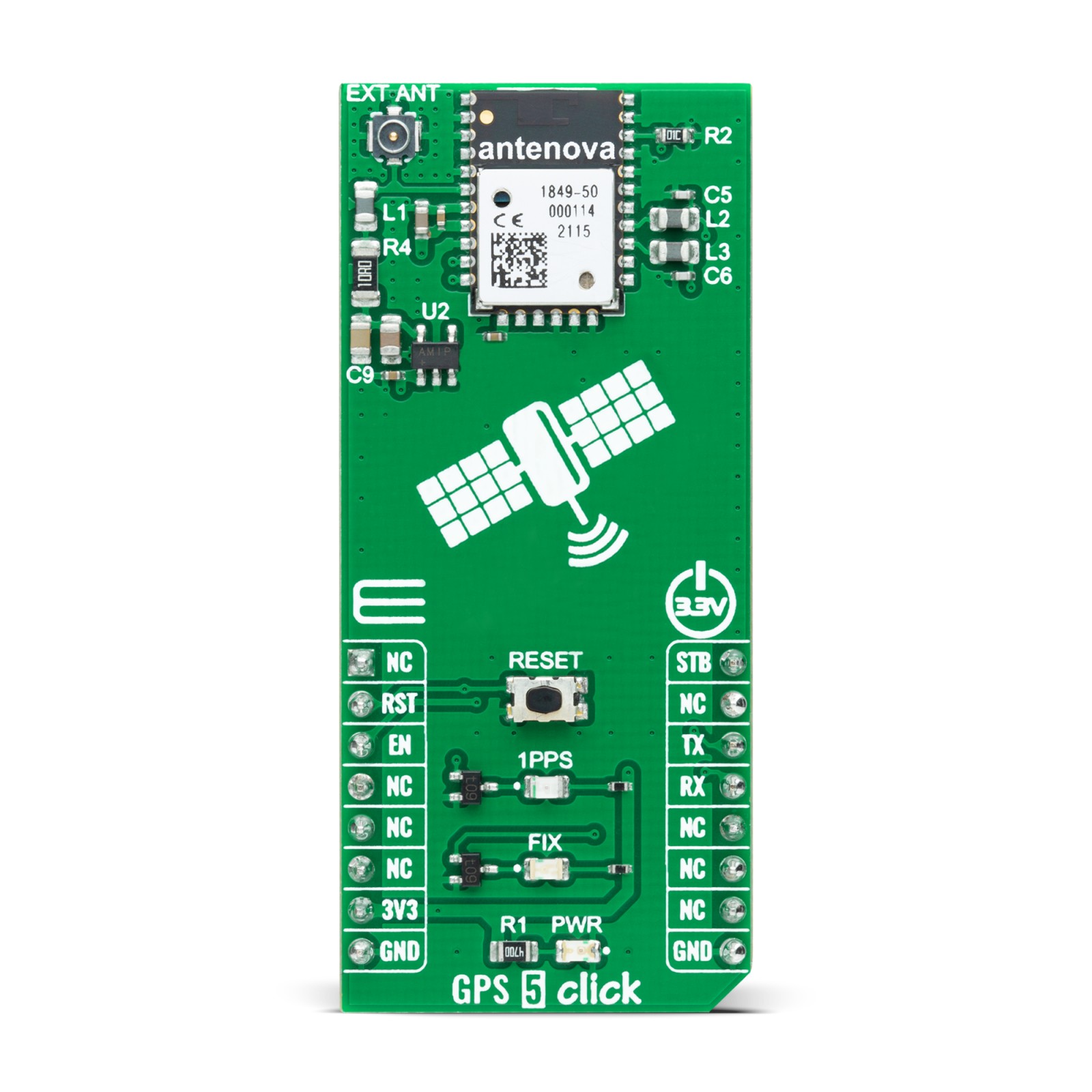
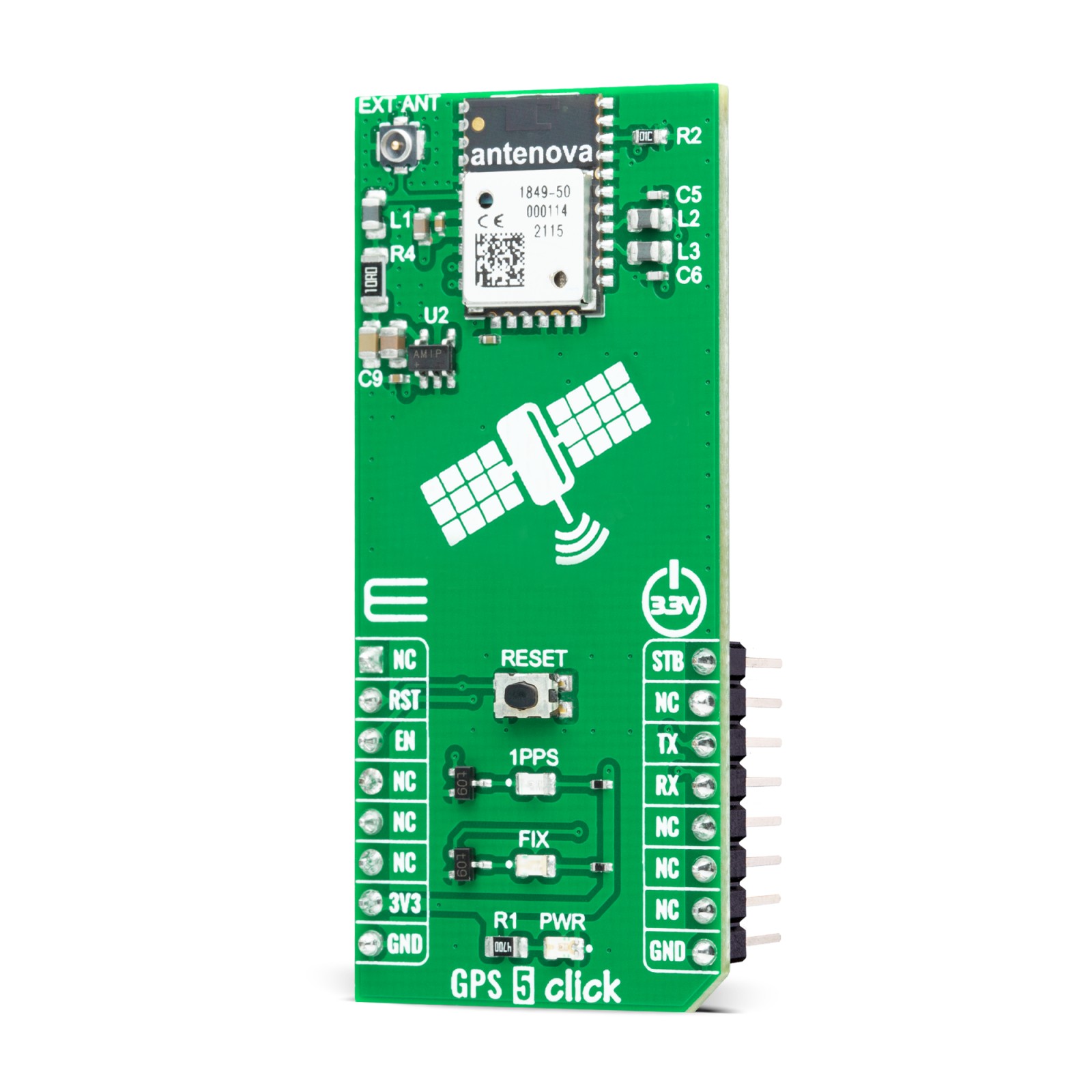
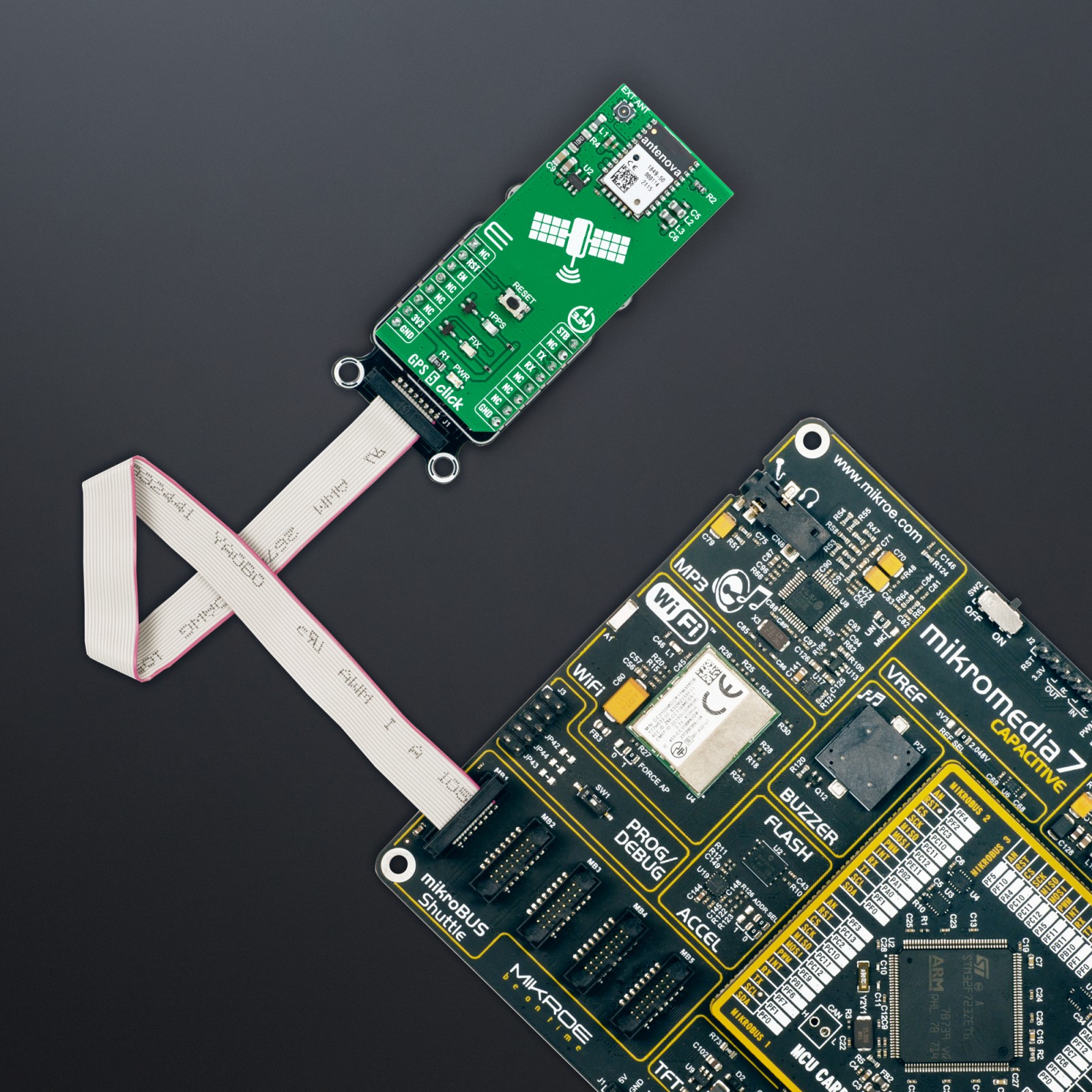
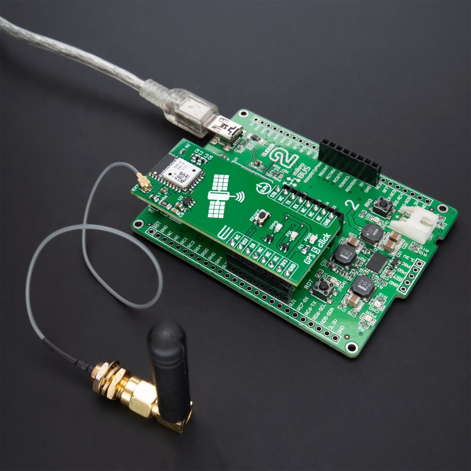
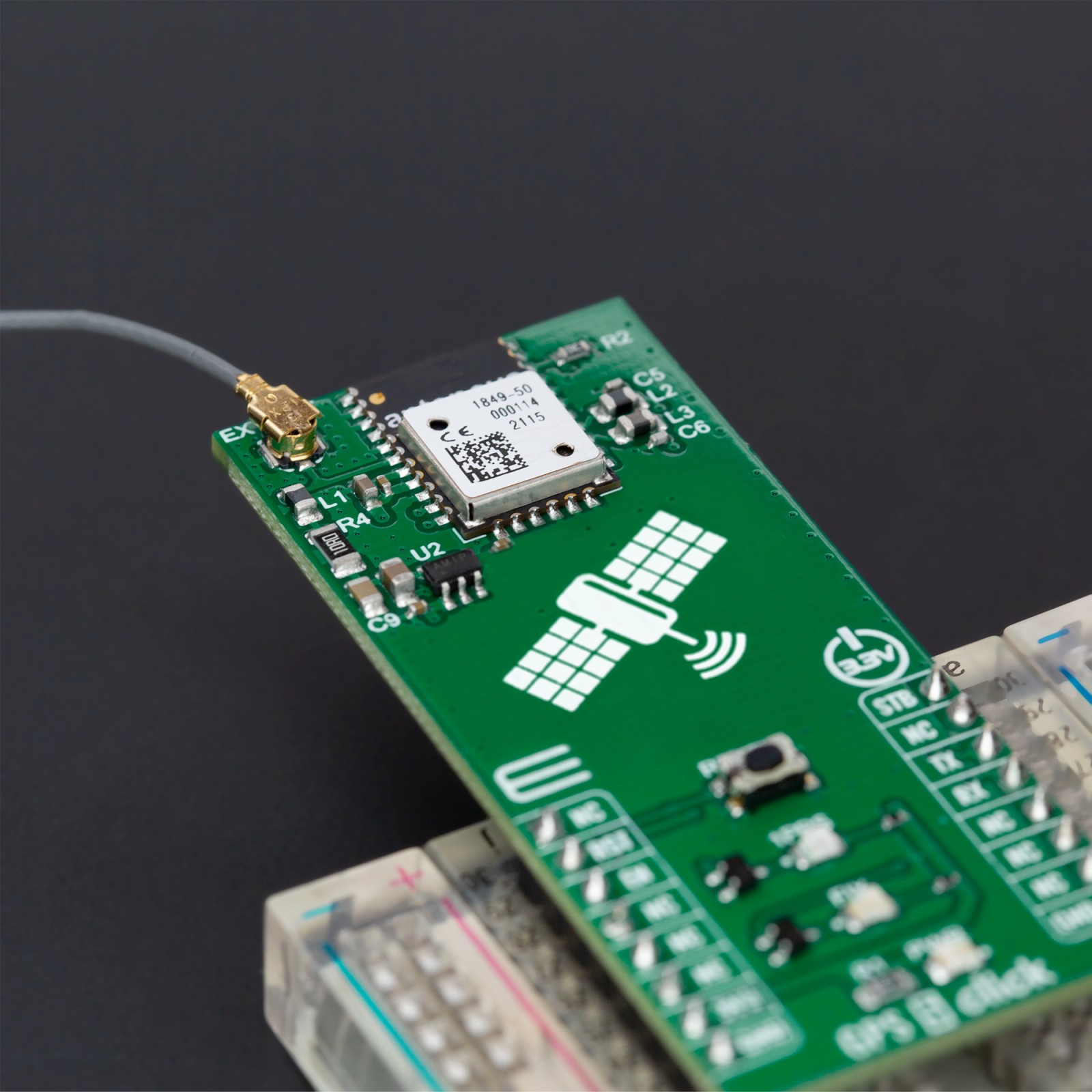
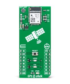
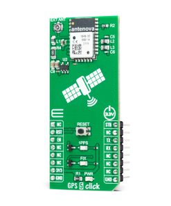
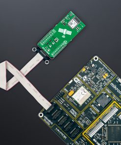
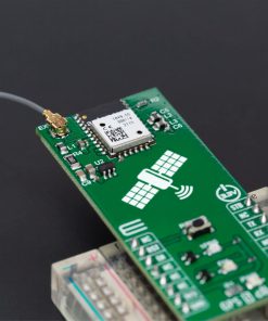
GPS 5 Click as its foundation uses the M20050-1, an integrated GNSS receiver module with an integrated antenna incorporating the MediaTek MT3333 flash chip from Antenova. The M20050-1 tracks 3 GNSS constellations concurrently (GPS+Galileo+GLONASS or GPS+Beidou) to considerably enhance the location and has configurable low power modes alongside acquisition and tracking sensitivity of -163dBm and -165dBm. This module offers indoor and outdoor multi-path detection and compensation and has an accurate 0.5ppm TXCO that ensures short TTFF besides an active interference cancellation (AIC) feature. This Click board is ideal for asset tracking/ personal safety, navigation devices, and sports equipment applications based on good attributes.
The M20050-1 has three power-saving modes: Standby, Backup, and Periodic. Standby mode is a power-saving mode initiated either with a hardware signal labeled as STB and routed on the PWM pin of the mikroBUS™ socket or by a software command. It shuts down the RF section of the module, putting the processor into Standby mode. The RTC is kept alive, and the RAM power is maintained to keep the module configuration. Periodic mode is a user-configurable mode that reduces current consumption by only waking the module for short periods to maintain FIX data.
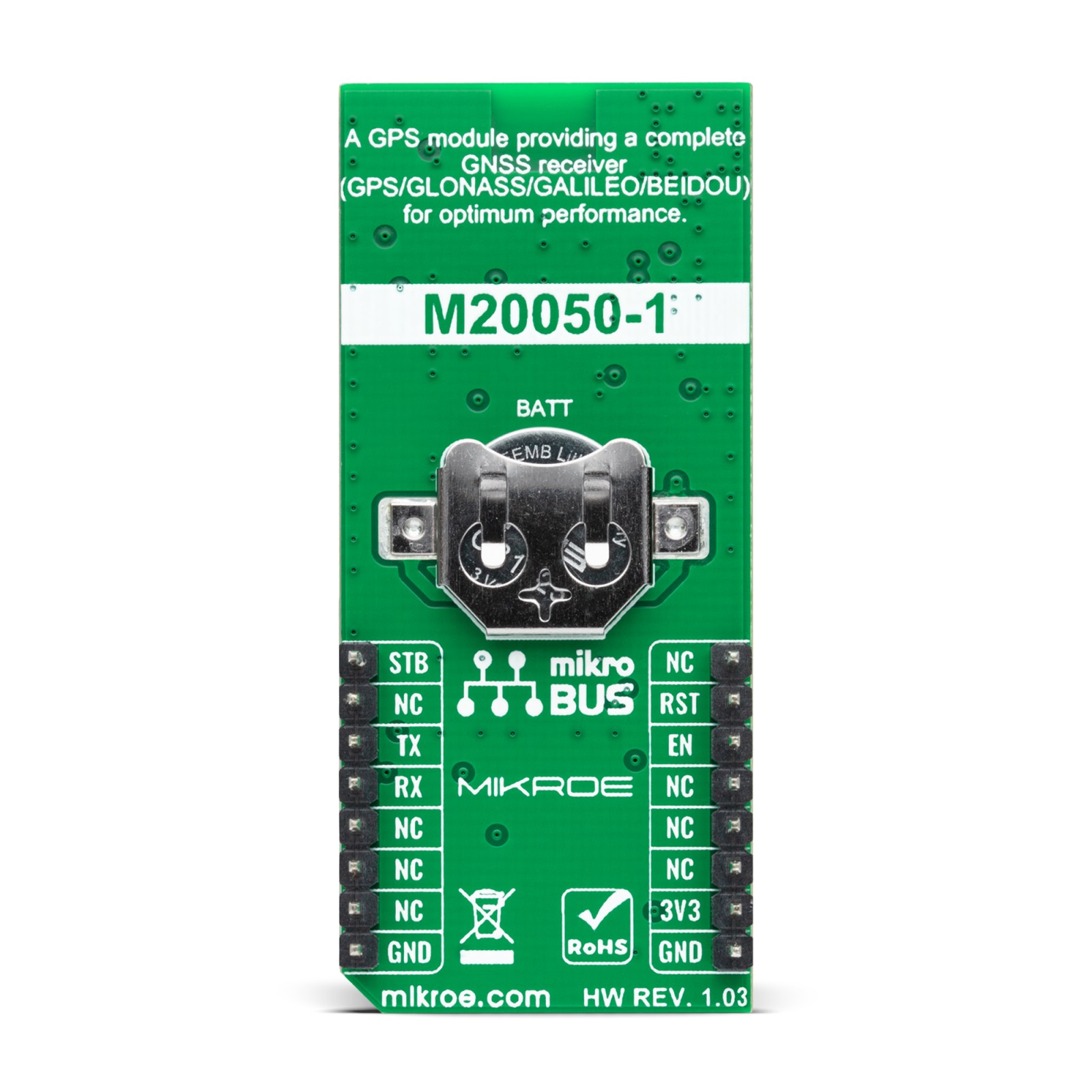
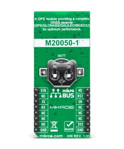
Backup mode is accessed due to the absence of the main board power supply VCC. For this reason, there is an additional backup power supply in the form of a battery that powers the RAM and RTC sections of the receiver and needs to be applied at all times for Backup mode to run correctly. Once initiated, the RTC and all configurations are saved along with any ephemeris data to allow quick TTFF once the VCC is re-applied.
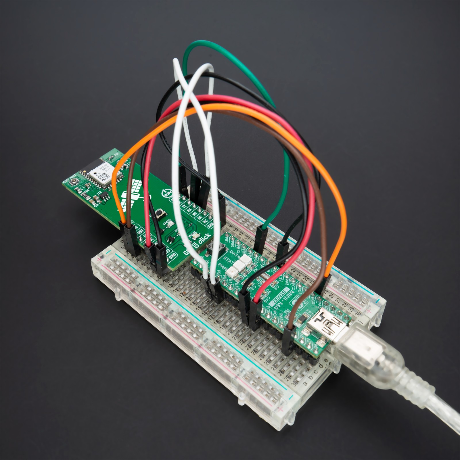
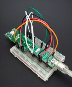
GPS 5 Click communicates with MCU using the UART interface with commonly used UART RX and TX pins operating at 115200bps by default configuration to transmit and exchange data with the host MCU. It also possesses an active-low reset signal routed on the RST pin of the mikroBUS™ socket that activates a hardware reset of the M20050-1. The reset function can also be used using an onboard RESET button.
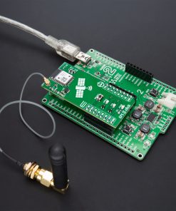
In addition to precise positioning, the GPS 5 Click also has an accurate timing signal indicated via a red LED indicator marked as 1PPS, a blue LED indicator marked with FIX, which shows once a GPS fix has been obtained, as well as the possibility of using an external active antenna which can also be found in our offer, activated through EN pin of the mikroBUS™ socket.
This Click board™ can be operated only with a 3.3V logic voltage level. The board must perform appropriate logic voltage level conversion before using MCUs with different logic levels. However, the Click board™ comes equipped with a library containing functions and an example code that can be used, as a reference, for further development.
Specifications
Type
GPS/GNSS
Applications
Can be used for asset tracking/ personal safety, navigation devices, and sports equipment applications
On-board modules
M20050-1 – compact GPS module receiver from Antenova
Key Features
Drop in GNSS receiver module (GPS/GLONASS/Galileo/Beidou), MediaTek MT3333 flash chip, low power consumption, interference cancellation, internally generated orbit prediction for short time to first fix, external antenna, and more
Interface
UART
Feature
No ClickID
Compatibility
mikroBUS™
Click board size
L (57.15 x 25.4 mm)
Input Voltage
3.3V
Pinout diagram
This table shows how the pinout on GPS 5 Click corresponds to the pinout on the mikroBUS™ socket (the latter shown in the two middle columns).
Onboard settings and indicators
Label | Name | Default | Description |
---|---|---|---|
LD1 | PWR | – | Power LED Indicator |
LD2 | 1PPS | – | Time Pulse LED Indicator |
LD3 | FIX | – | GPS Fix LED Indicator |
T1 | RESET | – | Reset Button |
GPS 5 Click electrical specifications
Description | Min | Typ | Max | Unit |
---|---|---|---|---|
Supply Voltage | – | 3.3 | – | V |
Operating Frequency | 1.559 | 1.575 | 1.609 | GHz |
Acquisition Sensitivity | – | -163 | – | dBm |
Tracking Sensitivity | – | -165 | – | dBm |
Operating Temperature Range | -40 | +25 | +85 | °C |
Software Support
We provide a library for the GPS 5 Click as well as a demo application (example), developed using MikroElektronika compilers. The demo can run on all the main MikroElektronika development boards.
Package can be downloaded/installed directly from NECTO Studio Package Manager(recommended way), downloaded from our LibStock™ or found on Mikroe github account.
Library Description
This library contains API for GPS 5 Click driver.
Key functions
-
gps5_set_rst_pin
This function sets the RST pin logic state. -
gps5_generic_read
This function reads a desired number of data bytes by using UART serial interface. -
gps5_parse_gngga
This function parses the GNGGA data from the read response buffer.
Example Description
This example demonstrates the use of GPS 5 Click board™ by reading and displaying the GPS coordinates.
void application_task ( void )
{
gps5_process( &gps5 );
if ( app_buf_len > ( sizeof ( ( char * ) GPS5_RSP_GNGGA ) + GPS5_GNGGA_ELEMENT_SIZE ) )
{
gps5_parser_application( app_buf );
}
}
The full application code, and ready to use projects can be installed directly from NECTO Studio Package Manager(recommended way), downloaded from our LibStock™ or found on Mikroe github account.
Other Mikroe Libraries used in the example:
- MikroSDK.Board
- MikroSDK.Log
- Click.GPS5
Additional notes and informations
Depending on the development board you are using, you may need USB UART click, USB UART 2 Click or RS232 Click to connect to your PC, for development systems with no UART to USB interface available on the board. UART terminal is available in all MikroElektronika compilers.
mikroSDK
This Click board™ is supported with mikroSDK – MikroElektronika Software Development Kit. To ensure proper operation of mikroSDK compliant Click board™ demo applications, mikroSDK should be downloaded from the LibStock and installed for the compiler you are using.
For more information about mikroSDK, visit the official page.