AudioAmp 8 Click
R745.00 ex. VAT
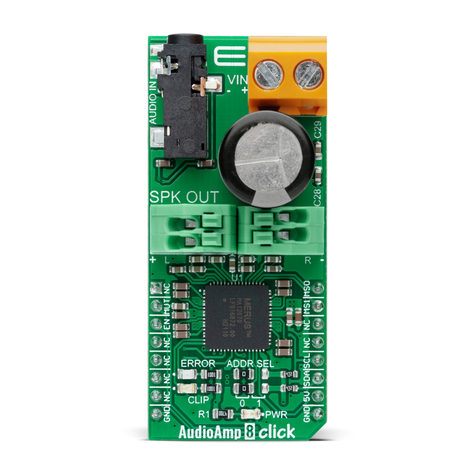
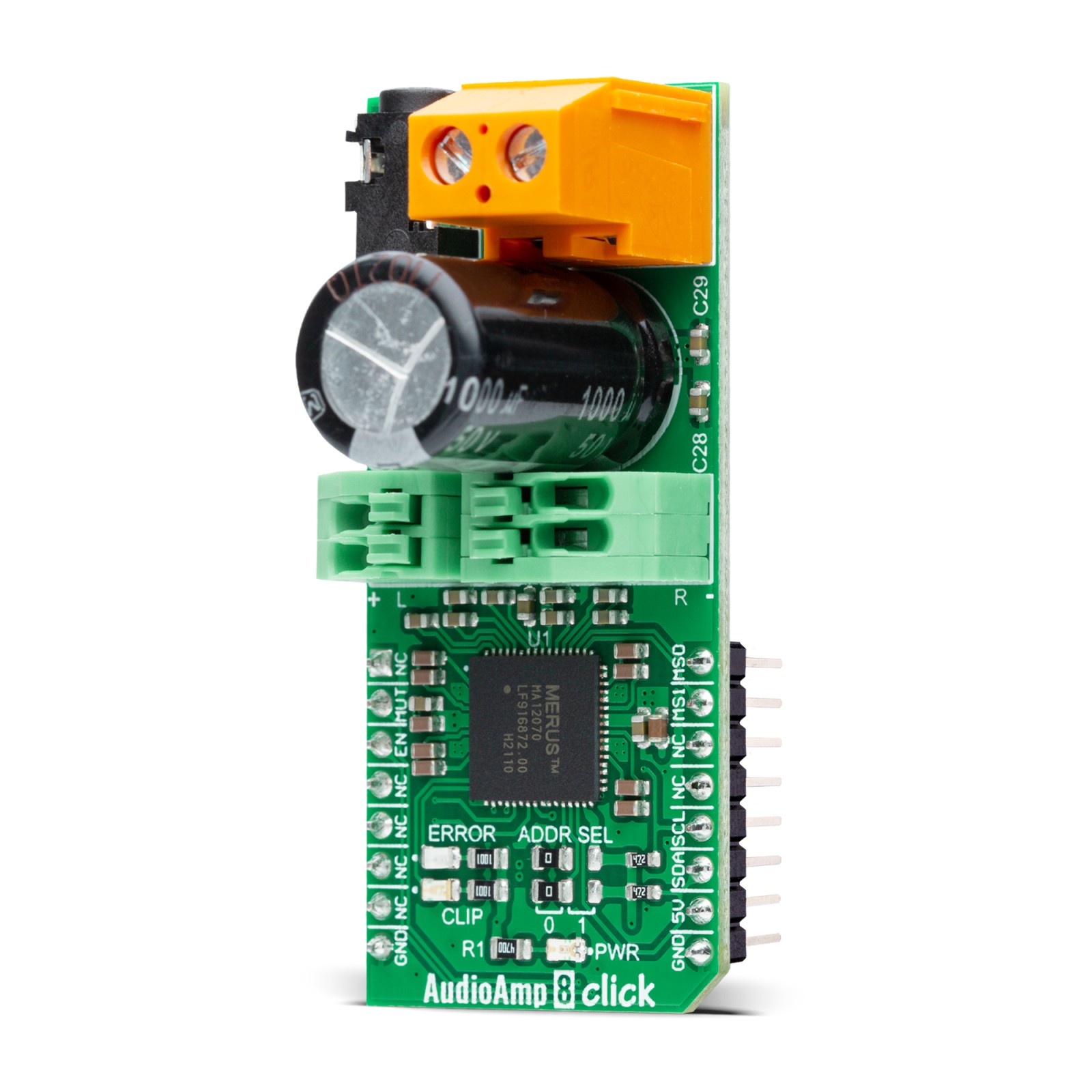
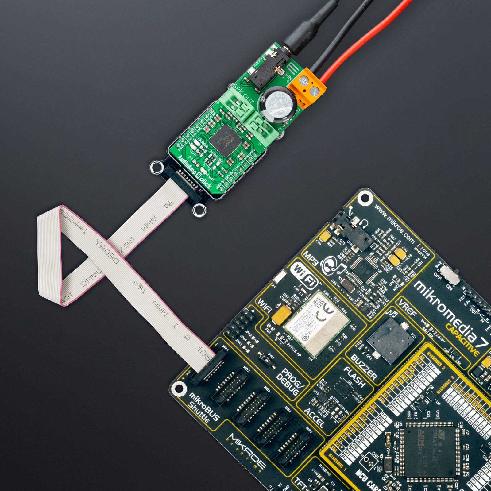
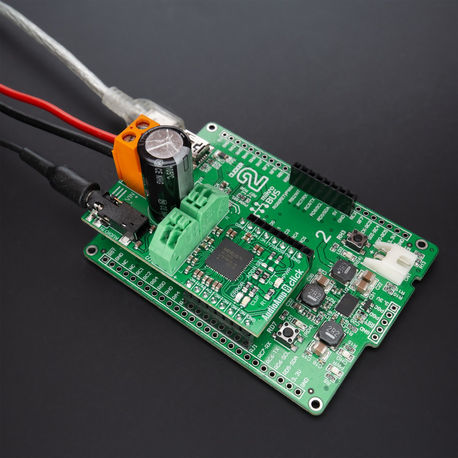
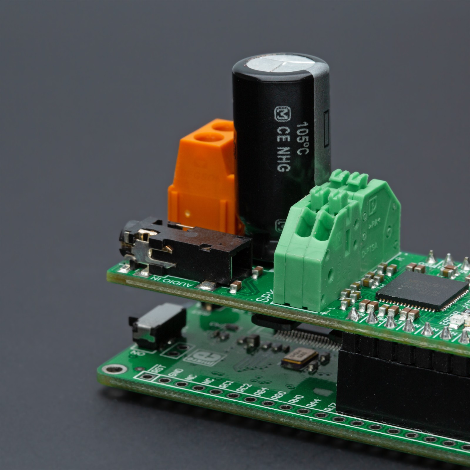
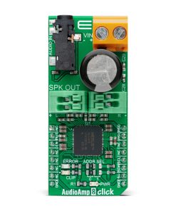
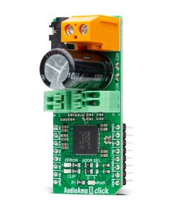
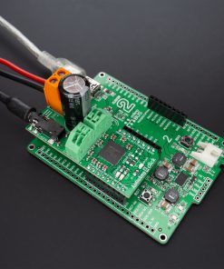
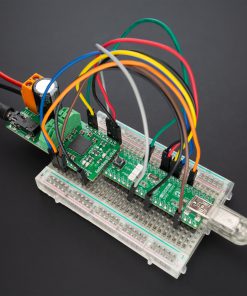
AudioAmp 8 Click is a compact add-on board that reproduces input audio signal at sound-producing output elements, with desired volume and power levels. This board features the MA12070, a super-efficient audio power amplifier from Infineon Technologies. This I2C configurable audio amplifier is based on proprietary multi-level switching technology, enabling low power loss during operation. It supports a supply voltage range from 4 to 26V, allowing it to be used in many applications. Besides, it is equipped with protection features, allowing a reliable operation. This Click board™ is suited for various types of consumer audio equipment applications.
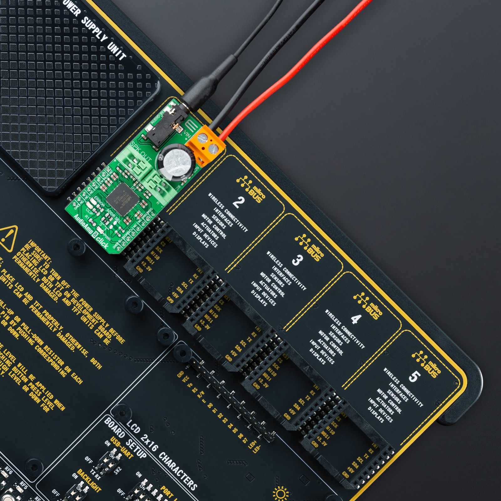
AudioAmp 8 Click is supported by a mikroSDK compliant library, which includes functions that simplify software development. This Click board™ comes as a fully tested product, ready to be used on a system equipped with the mikroBUS™ socket.
Stock: Lead-time applicable.
| 5+ | R707.75 |
| 10+ | R670.50 |
| 15+ | R633.25 |
| 20+ | R609.41 |
How does it work?
AudioAmp 8 Click as its foundation uses the MA12070, a super-efficient audio power amplifier based on proprietary multi-level switching technology that enables low power loss during operation from Infineon Technologies. The MA12070 is equipped with an intelligent power management algorithm that applies automatic power mode selection during audio playback. In this state, the amplifier will seamlessly transition between three different power modes depending on the audio level to achieve optimal power loss, audio performance, and EMI. Alternatively, it is also possible to manually select the desired power mode for the MA12070 via a serial interface.

The MA12070 communicates with MCU using the standard I2C 2-Wire interface that supports Standard (100 kHz) and Fast (400 kHz) modes of operation. It has a 7-bit slave address with the first five MSBs fixed to 01000. The address pins are programmed by the user and determine the value of the last two LSBs of the slave address, which can be selected by positioning onboard SMD jumpers labeled as ADDR SEL to an appropriate position marked as 0 or 1.
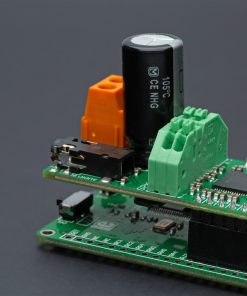
This Click board™ supports an external power supply for the amplifier, which can be connected to the input terminal labeled as VIN and should be within the range of 6V to 26V, while the input audio can be brought to the input jack labeled as AUDIO IN and after specific processing reproduced on the speakers of the desired channel SPK OUT.
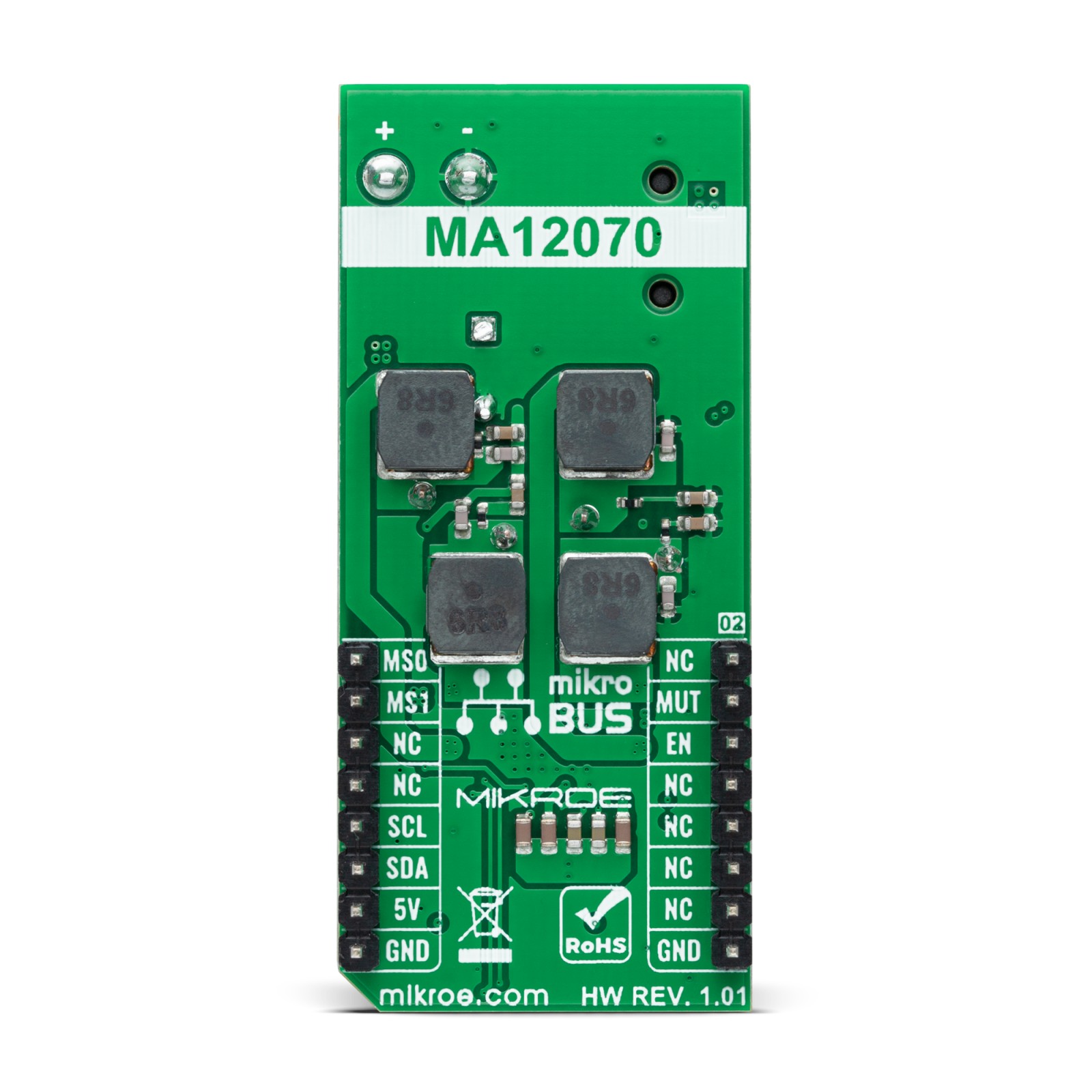
The MA12070 is highly flexible regarding the configuration of the four power amplifier channels. It can be set to four different output configurations by setting the configuration pins MS0 and MS1, routed to the INT and PWM pins of the mikroBUS™ socket. In addition to these pins, this Click board™ uses a few more pins of the mikroBUS™ socket. The Enable pin, labeled as EN and routed to the CS pin of the mikroBUS™ socket, optimizes power consumption used for power ON/OFF purposes, while the MUT pin routed to the RST pin allows users to mute audio on connected speakers.
Besides, it is possible to detect operational irregularities, such as overcurrent and short-circuit detection. An indication of such a condition is performed using the red LED indicator labeled as ERROR, alongside an audio clipping indication accomplished using the blue LED indicator labeled as CLIP which indicates when audio output is close to clipping.
This Click board™ can operate with either 3.3V or 5V logic voltage levels selected via the VIO SEL jumper. This way, both 3.3V and 5V capable MCUs can use the communication lines properly. Also, this Click board™ comes equipped with a library containing easy-to-use functions and an example code that can be used, as a reference, for further development.
Specifications
Type
Amplifier
Applications
Can be used for various types of consumer audio equipment applications
On-board modules
MA12070 – super-efficient audio power amplifier from Infineon Technologies
Key Features
Proprietary multi-level switching technology, high power efficiency, high audio performance, low power consumption, flexible output stage configuration, protection feature, and more
Interface
I2C
Feature
No ClickID
Compatibility
mikroBUS™
Click board size
L (57.15 x 25.4 mm)
Input Voltage
3.3V or 5V,External
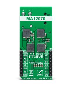
Pinout diagram
This table shows how the pinout on AudioAmp 8 Click corresponds to the pinout on the mikroBUS™ socket (the latter shown in the two middle columns).
Onboard settings and indicators
| Label | Name | Default | Description |
|---|---|---|---|
| LD1 | PWR | – | Power LED Indicator |
| LD2 | ERROR | – | Error LED Indicator |
| LD3 | CLIP | – | Audio Clipping LED Indicator |
| JP1-JP2 | ADDR SEL | Left | I2C Address Selection 0/1: Left position 0, Right position 1 |
| JP3 | VIO SEL | Left | Logic Voltage Level Selection 3V3/5V: Left position 3V3, Right position 5V |
AudioAmp 8 Click electrical specifications
| Description | Min | Typ | Max | Unit |
|---|---|---|---|---|
| Supply Voltage | 3.3 | – | 5 | V |
| External Power Supply Voltage VIN | 4 | – | 26 | V |
| Output Power (per channel) | – | 80 | – | W |
Software Support
We provide a library for the Audio Amp 8 Click as well as a demo application (example), developed using MIKROE compilers. The demo can run on all the main MIKROE development boards.
Library Description
Package can be downloaded/installed directly from NECTO Studio Package Manager (recommended), downloaded from our LibStock™ or found on MIKROE github account.
Key functions:
audioamp8_cfg_setup– Config Object Initialization function.audioamp8_init– Initialization function.audioamp8_default_cfg– Click Default Configuration function.
Examples description
This library contains API for AudioAmp 8 Click driver. The library initializes and defines the I2C bus drivers to write and read data from registers.
void application_init ( void )
{
    log_cfg_t log_cfg;  /**< Logger config object. */
    audioamp8_cfg_t audioamp8_cfg;  /**< Click config object. */

    // Logger initialization.
    LOG_MAP_USB_UART( log_cfg );
    log_cfg.level = LOG_LEVEL_DEBUG;
    log_cfg.baud = 115200;
    log_init( &logger, &log_cfg );
    log_info( &logger, " Application Init " );

    // Click initialization.
    audioamp8_cfg_setup( &audioamp8_cfg );
    AUDIOAMP8_MAP_MIKROBUS( audioamp8_cfg, MIKROBUS_1 );
    err_t init_flag = audioamp8_init( &audioamp8, &audioamp8_cfg );
    if ( I2C_MASTER_ERROR == init_flag )
    {
        log_error( &logger, " Application Init Error. " );
        log_info( &logger, " Please, run program again... " );

        for ( ; ; );
    }

    audioamp8_default_cfg ( &audioamp8 );
    log_info( &logger, " Application Task " );

    audioamp8_btl_config( &audioamp8 );
    Delay_ms( 100 );

    pwr_mode.manual_pm = AUDIOAMP8_SET_MANUAL_PWR_MODE;
    pwr_mode.pm_man    = AUDIOAMP8_PM_MAN_3;
    pwr_mode.mthr_1to2 = AUDIOAMP8_SET_MTHR_1TO2_DEFAULT;
    pwr_mode.mthr_2to1 = AUDIOAMP8_SET_MTHR_2TO1_DEFAULT;
    pwr_mode.mthr_2to3 = AUDIOAMP8_SET_MTHR_2TO3_DEFAULT;
    pwr_mode.mthr_3to2 = AUDIOAMP8_SET_MTHR_3TO2_DEFAULT;
    audioamp8_set_config_power_mode( &audioamp8, pwr_mode );
    Delay_ms( 100 );

    pm_profile.pm_profile = AUDIOAMP8_PM_PROFILE_3;
    pm_profile.pm3_man_sh = AUDIOAMP8_SCHEME_C;
    audioamp8_set_config_power_mode_profile( &audioamp8, pm_profile );
    Delay_ms( 100 );

    audioamp8_set_mute( &audioamp8, AUDIOAMP8_SET_DISABLE );
    log_printf( &logger, "-------------------------rn" );
    Delay_ms( 1000 );
}
The full application code, and ready to use projects can be installed directly from NECTO Studio Package Manager (recommended), downloaded from our LibStock™ or found on MIKROE github account.
Other MIKROE Libraries used in the example:
- MikroSDK.Board
- MikroSDK.Log
- Click.AudioAmp8
Additional notes and informations
Depending on the development board you are using, you may need USB UART click, USB UART 2 click or RS232 click to connect to your PC, for development systems with no UART to USB interface available on the board. The terminal available in all MIKROE compilers, or any other terminal application of your choice, can be used to read the message.
mikroSDK
This Click board™ is supported with mikroSDK – MIKROE Software Development Kit. To ensure proper operation of mikroSDK compliant Click board™ demo applications, mikroSDK should be downloaded from the LibStock and installed for the compiler you are using.
For more information about mikroSDK, visit the official page.
Resources
Downloads
| Weight | 33 g |
|---|---|
| Brand | MikroElektronika |

