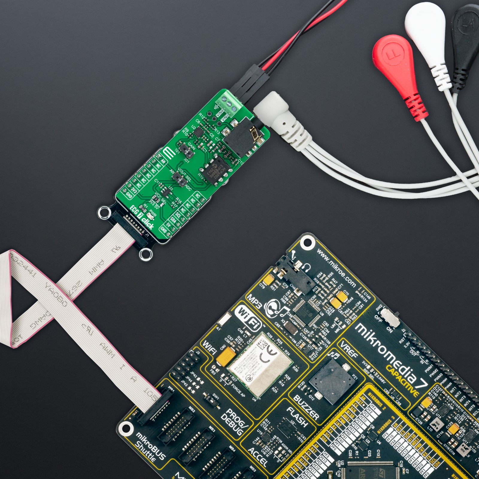
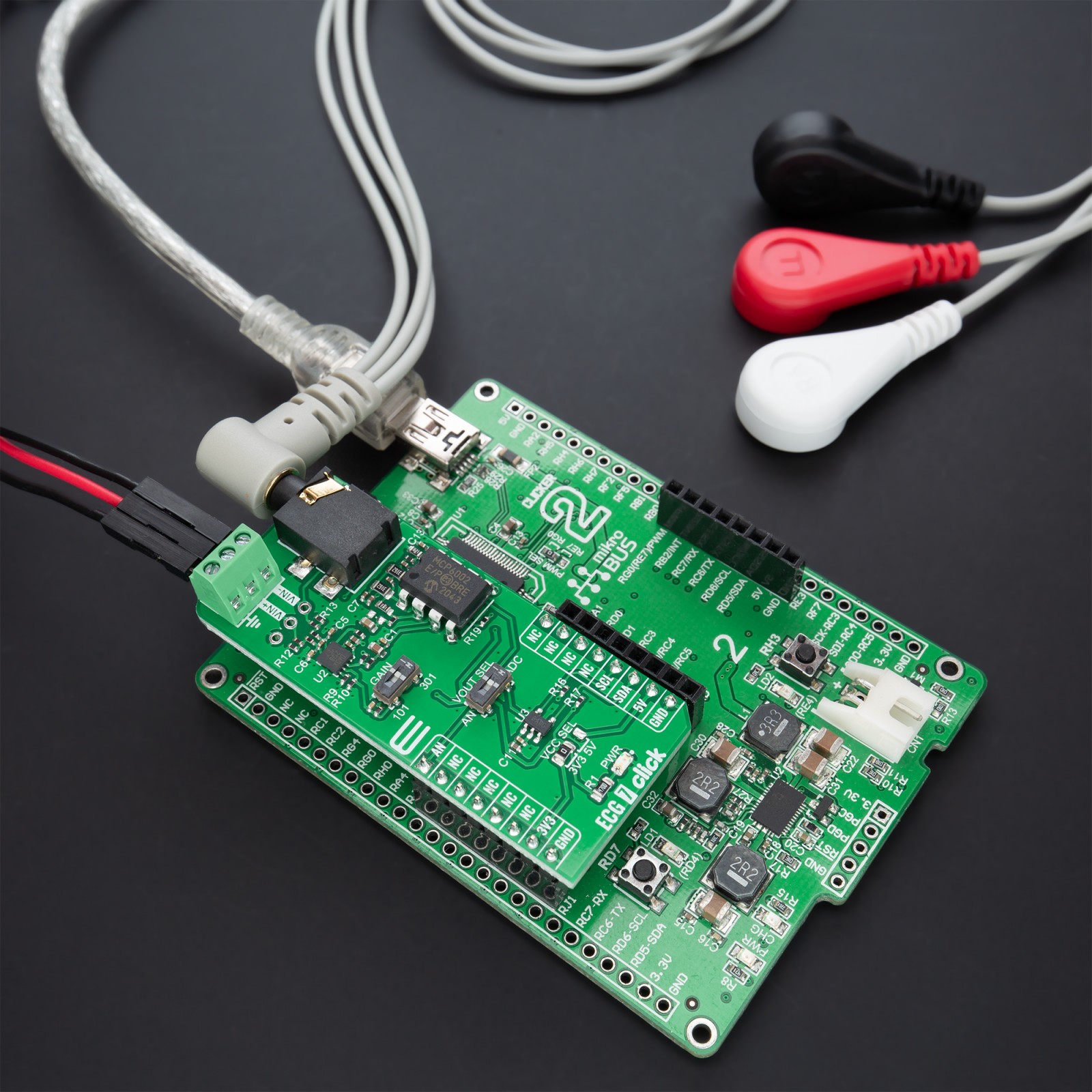
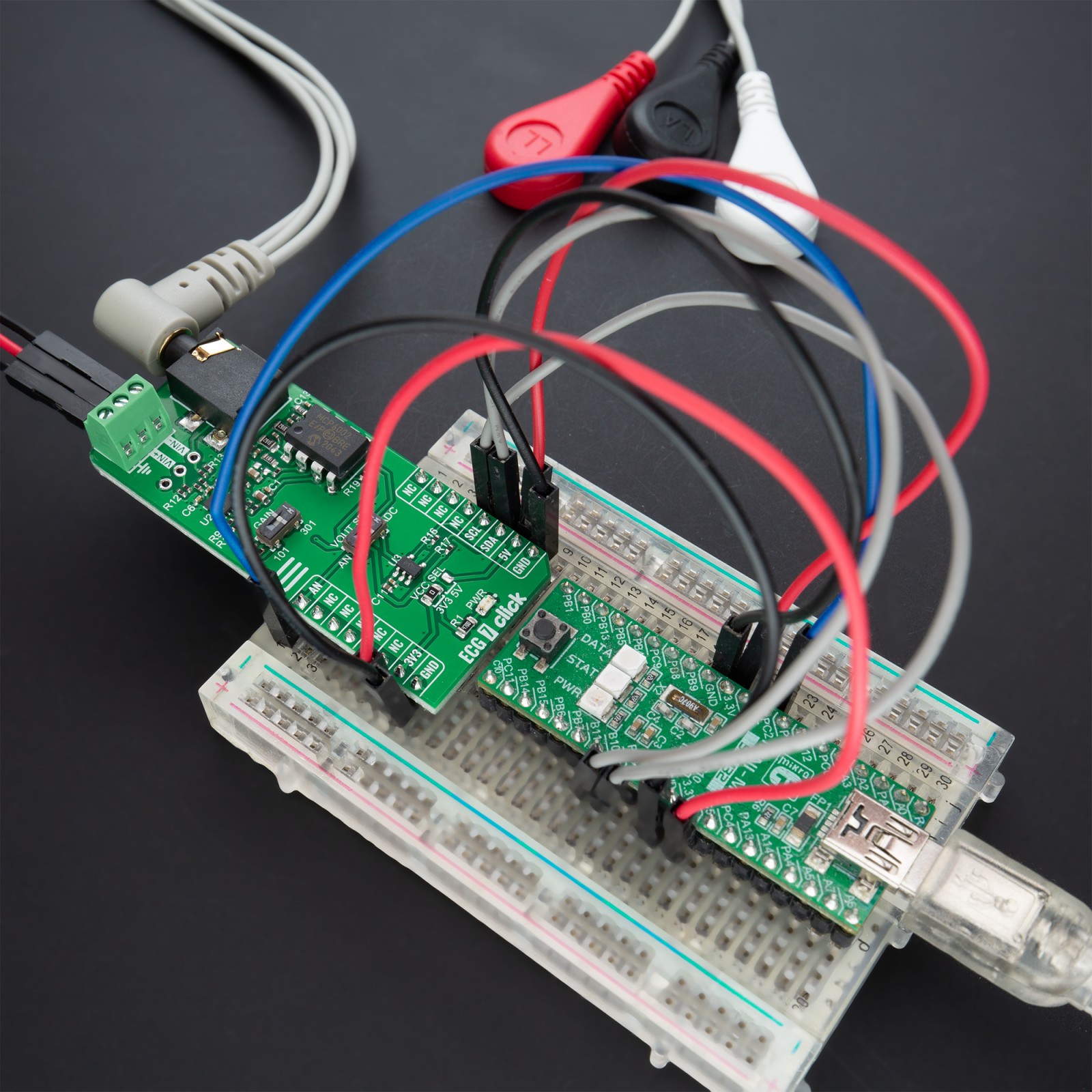
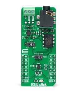
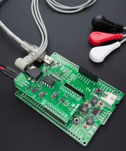
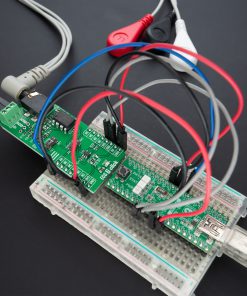
NOTE: This Click board™ represents a development and prototyping tool. It is not intended to be used for a patient’s medical treatment and should not be used to diagnose or treat any conditions.
How does it work?
ECG 7 Click as its foundation uses the MCP6N16, a zero-drift instrumentation amplifier designed for single-supply operation with rail-to-rail input and output performance from Microchip. The design of the MCP6N16 is based on a current feedback architecture which allows for the output voltage to be independently set regardless of the input common-mode voltage. Its internal offset correction gives high DC precision, low offset and drift, and negligible noise.
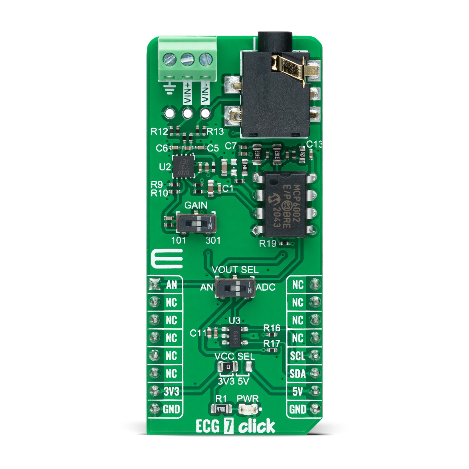
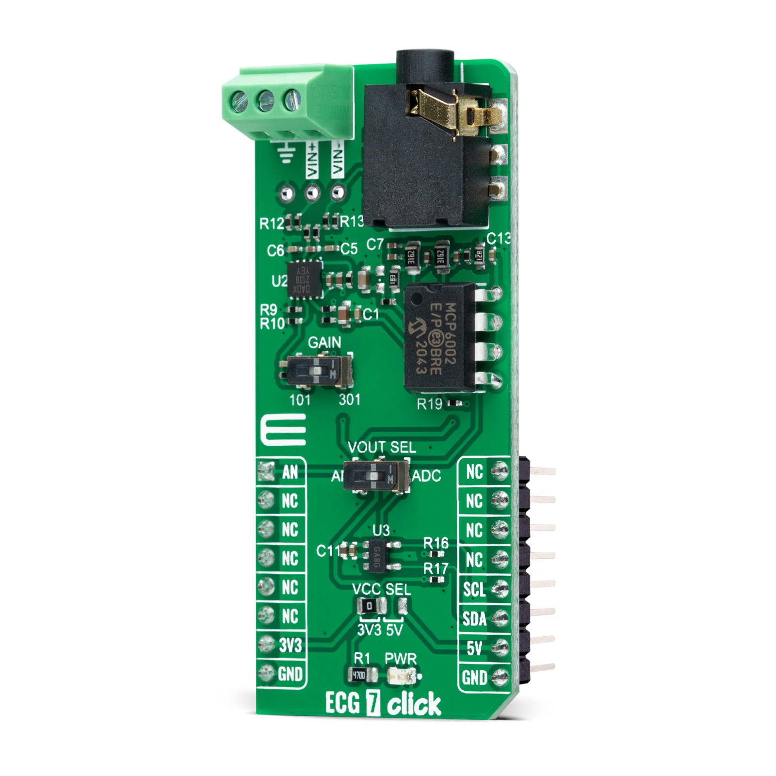
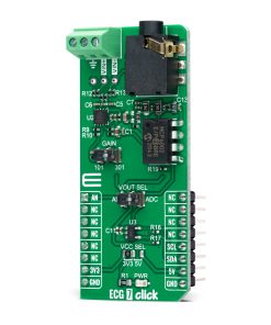
The head part of the board represents a differential amplification stage based on the MCP6N16, with the RC input filter providing a low-pass function for differential mode signals. This part also comes with selectable gain for the MCP6N16, performed by an onboard switch marked as GAIN, allowing users to quickly set the gain on the MCP6N16 to either 101V/V or 301V/V by setting the switch to an appropriate position. After that, the signal from MCP6N16 goes through amplification and buffering by the MCP6002 operational amplifier. Then the signal is ready for further processing in analog or digital format.
As mentioned before, this Click board™ possesses two ways to communicate with the MCU. The output voltage of the MCP6002 Op-Amp can be converted to a digital value using MCP3221, a successive approximation A/D converter from Microchip, using a 2-wire I2C compatible interface, or can be sent directly to an analog pin of the mikroBUS™ socket labeled as AN. Selection is performed by onboard SMD switch labeled as VOUT SEL to an appropriate position marked as AN and ADC. Using MCP3221 and I2C interface, data transfers at rates of up to 100kbit/s in the Standard and 400kbit/s in the Fast Mode.
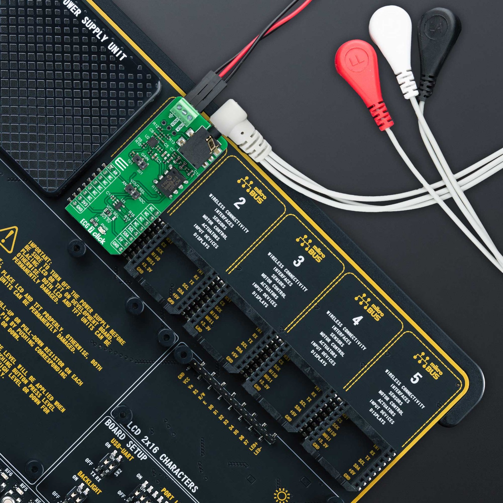
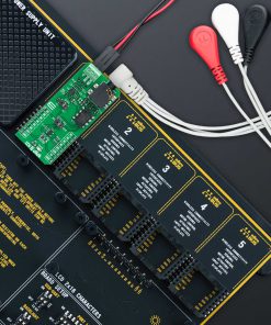
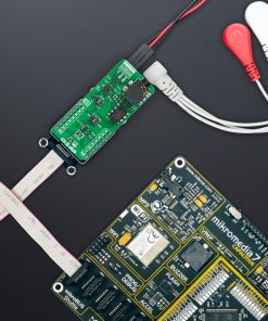
In addition to the 3.5mm jack connector reserved for connecting the ECG/EMG cable with ECG electrodes, this Click board™ offers the possibility of connecting electrodes through screw terminals labeled as VIN+ and VIN-, or unpopulated header if the electrode connection does not match the jack connector.
This Click board™ can operate with both 3.3V and 5V logic voltage levels selected via the VCC SEL jumper. This way, it is allowed for both 3.3V and 5V capable MCUs to use the communication lines properly. However, the Click board™ comes equipped with a library containing easy-to-use functions and an example code that can be used, as a reference, for further development.
Specifications
Type
Biometrics,ECG
Applications
Can be used for medical remote diagnostic equipment applications, such as electrocardiogram (ECG) measurement
On-board modules
MCP6N16 – single zero-drift instrumentation amplifier from Microchip
Key Features
Low power consumption, high DC precision, gain selection, allow to process the output signal in analog or digital form, flexible ECG signal connections, and more
Interface
Analog,I2C
Feature
No ClickID
Compatibility
mikroBUS™
Click board size
L (57.15 x 25.4 mm)
Input Voltage
3.3V or 5V
Pinout diagram
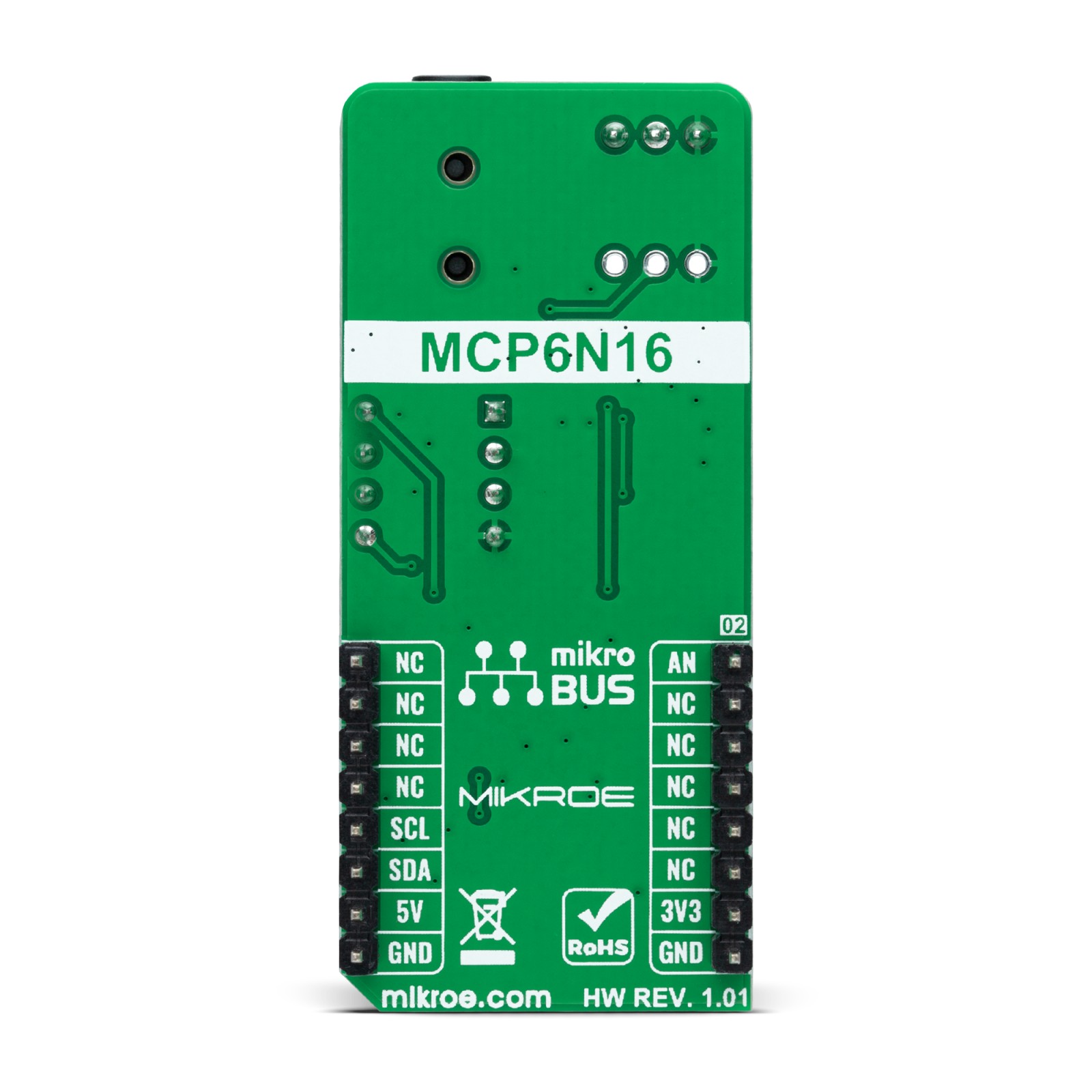
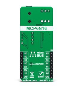
This table shows how the pinout on ECG 7 Click corresponds to the pinout on the mikroBUS™ socket (the latter shown in the two middle columns).
Onboard settings and indicators
Label | Name | Default | Description |
---|---|---|---|
LD1 | PWR | – | Power LED Indicator |
JP1 | VCC SEL | Left | Logic Level Voltage Selection 3V3/5V: Left position 3V3, Right position 5V |
SW1 | GAIN | Right | MCP6N16 Gain Selection 101/301: Left position 101, Right position 301 |
SW2 | VOUT SEL | Right | Output Voltage A/D Selection AN/ADC: Left position AN, Right position ADC |
J1 | – | Unpopulated | ECG Signal Connection Header |
ECG 7 Click electrical specifications
Description | Min | Typ | Max | Unit |
---|---|---|---|---|
Supply Voltage | 3.3 | – | 5 | V |
Operating Temperature Range | -40 | +25 | +120 | °C |
Software Support
We provide a library for the ECG 7 Click as well as a demo application (example), developed using MikroElektronika compilers. The demo can run on all the main MikroElektronika development boards.
Package can be downloaded/installed directly from NECTO Studio Package Manager(recommended way), downloaded from our LibStock™ or found on Mikroe github account.
Library Description
This library contains API for ECG 7 Click driver.
Key functions
-
ecg7_read_raw_adc
This function reads raw ADC value. -
ecg7_read_voltage
This function reads raw ADC value and converts it to proportional voltage level. -
ecg7_set_vref
This function sets the voltage reference for ECG 7 click driver.
Example Description
This example demonstrates the use of ECG 7 Click board™ by reading and displaying the voltage from VOUT BUFF which can be visualized on the SerialPlot application.
void application_task ( void )
{
float ecg7_an_voltage = 0;
if ( ECG7_OK == ecg7_read_voltage ( &ecg7, &ecg7_an_voltage ) )
{
log_printf( &logger, "%.3frn", ecg7_an_voltage );
Delay_ms ( 4 );
}
}
The full application code, and ready to use projects can be installed directly from NECTO Studio Package Manager(recommended way), downloaded from our LibStock™ or found on Mikroe github account.
Other Mikroe Libraries used in the example:
- MikroSDK.Board
- MikroSDK.Log
- Click.ECG7
Additional notes and informations
Depending on the development board you are using, you may need USB UART click, USB UART 2 Click or RS232 Click to connect to your PC, for development systems with no UART to USB interface available on the board. UART terminal is available in all MikroElektronika compilers.
mikroSDK
This Click board™ is supported with mikroSDK – MikroElektronika Software Development Kit. To ensure proper operation of mikroSDK compliant Click board™ demo applications, mikroSDK should be downloaded from the LibStock and installed for the compiler you are using.
For more information about mikroSDK, visit the official page.