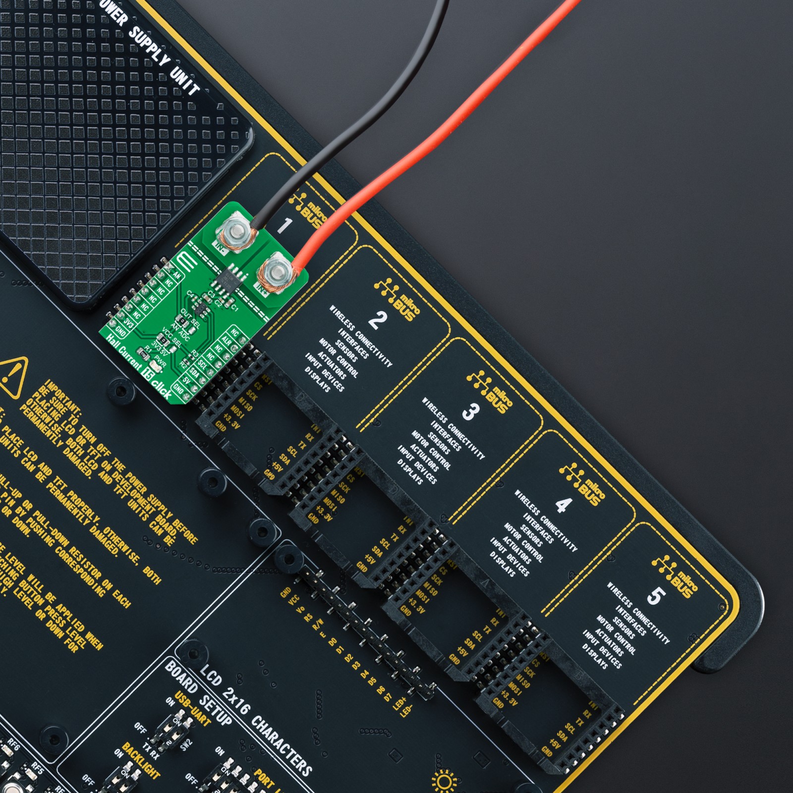
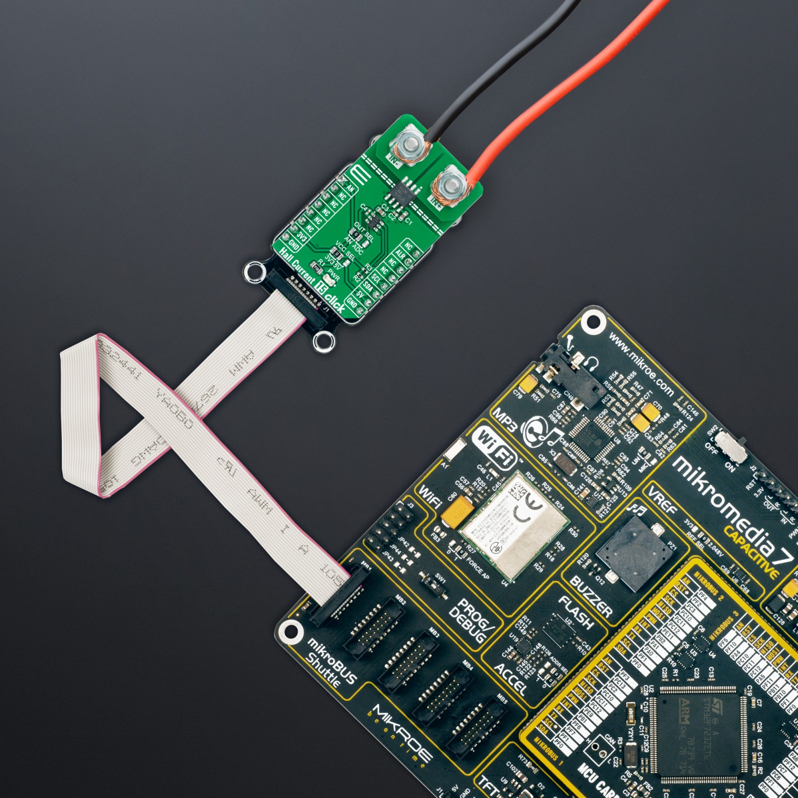
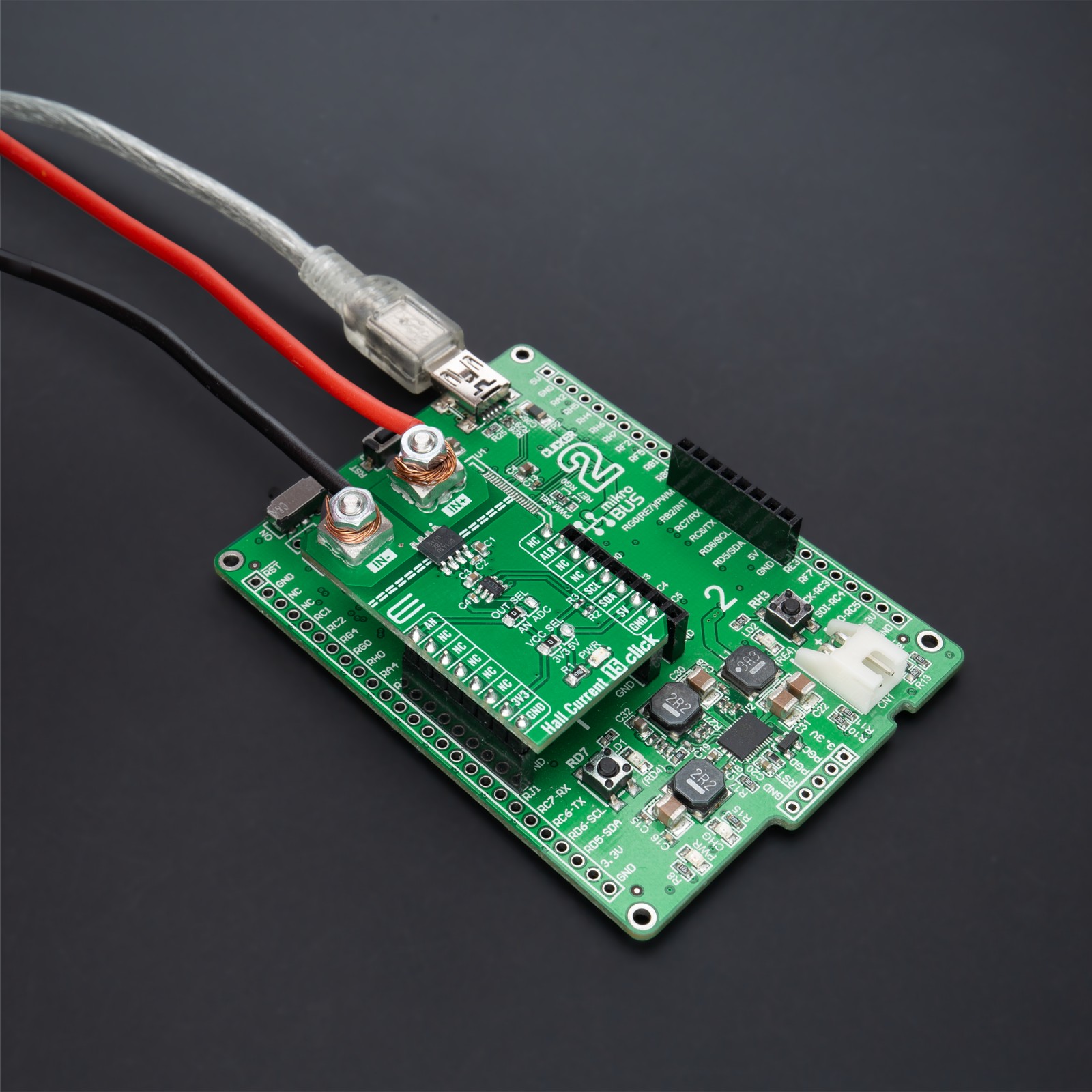
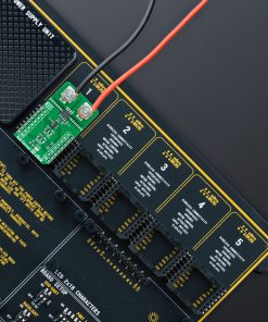
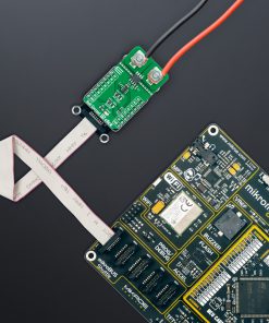
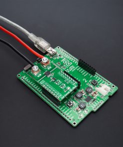
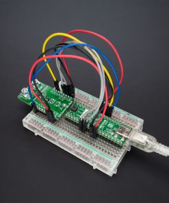
DO NOT TOUCH THE BOARD WHILE THE LOAD IS CONNECTED!
Note: This Click board™ needs to be used by trained personnel only while applying high voltages. Special care should be taken when working with hazardous voltage levels.
How does it work?
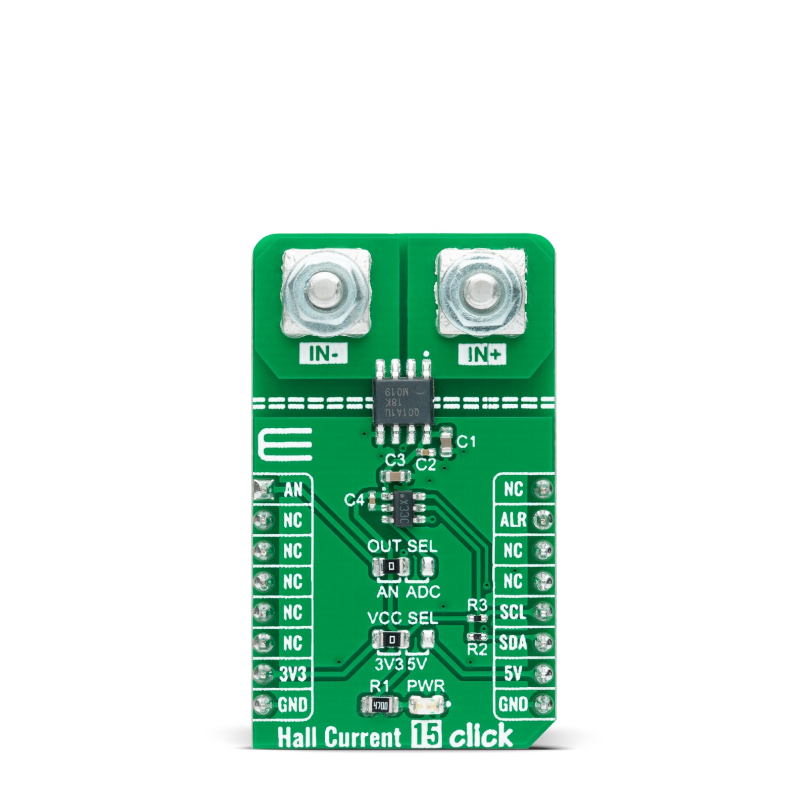
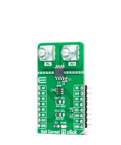
Hall Current 15 Click as its foundation uses the TMCS1101-Q1, a precise Hall-effect current sensor featuring a 600V isolation working voltage, <1.5% full-scale error across temperature, and device options providing both unidirectional and bidirectional current sensing from Texas Instruments. The input current flows through an internal 1.8mΩ conductor that generates a magnetic field measured by an integrated Hall-effect sensor and amplified by a precision signal chain. The device has a bandwidth of 80kHz and can be used for AC and DC current measurements. It is optimized for high accuracy and temperature stability, with offset and sensitivity compensated across the operating temperature range.
This Click board™ possesses two ways to communicate with the MCU. The analog output signal of the TMCS1101-Q1 can be converted to a digital value using ADC101C021, a 10-bit resolution analog-to-digital converter from Texas Instruments using a 2-wire I2C compatible interface, or can be sent directly to an analog pin of the mikroBUS™ socket labeled as AN. Selection can be performed by onboard SMD switch labeled as OUT SEL, setting it to an appropriate position marked as AN or ADC. The ADC101C021 can transfer data supporting modes up to High-Speed, alongside its alert function, which provides an interrupt routed to the ALR pin of the mikroBUS™ socket activated when analog input violates a programmable upper or lower limit value.
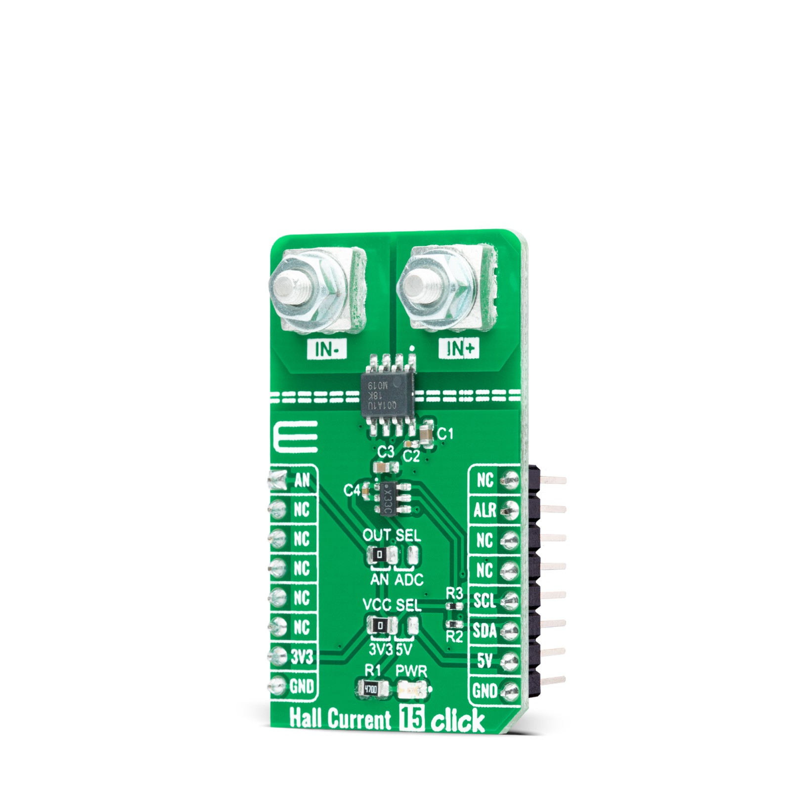
Also, this Click board™ should be connected in series with the load. The current is measured by two onboard terminal connectors, one terminal block for the positive and the other for the negative current input.
This Click board™ can operate with both 3.3V and 5V logic voltage levels selected via the VCC SEL jumper. This way, it is allowed for both 3.3V and 5V capable MCUs to use the communication lines properly. However, the Click board™ comes equipped with a library containing easy-to-use functions and an example code that can be used, as a reference, for further development.
Specifications
Type
Current sensor,Measurements
Applications
Can be used for AC or DC current-sensing in industrial and commercial systems, motor and load control, power factor correction, overcurrent protection, and many more
On-board modules
TMCS1101-Q1 – galvanically isolated Hall-effect current sensor capable of DC or AC current measurement from Texas Instruments
Key Features
High accuracy and precision, excellent linearity, and temperature stability, 3kVRMS isolation rating, robust 600V lifetime working voltage, bidirectional and unidirectional current sensing, and more
Interface
Analog,I2C
Feature
No ClickID
Compatibility
mikroBUS™
Click board size
L (57.15 x 25.4 mm)
Input Voltage
3.3V or 5V
Pinout diagram
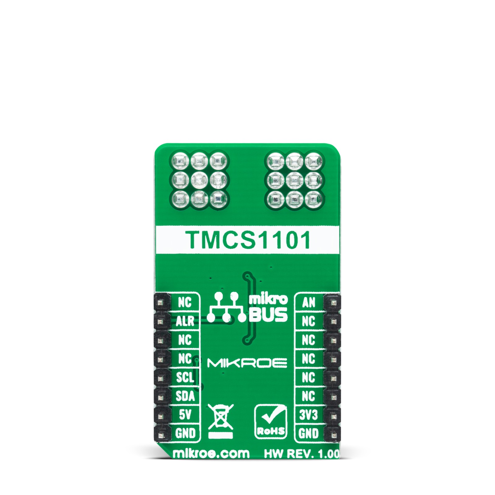
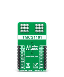
This table shows how the pinout on Hall Current 15 Click corresponds to the pinout on the mikroBUS™ socket (the latter shown in the two middle columns).
Onboard settings and indicators
Label | Name | Default | Description |
---|---|---|---|
LD1 | PWR | – | Power LED Indicator |
JP1 | VCC SEL | Left | Logic Level Voltage Selection 3V3/5V: Left position 3V3, Right position 5V |
JP2 | OUT SEL | Left | Output Voltage A/D Selection AN/ADC: Left position AN, Right position ADC |
Hall Current 15 Click electrical specifications
Description | Min | Typ | Max | Unit |
---|---|---|---|---|
Supply Voltage | 3.3 | – | 5 | V |
Measurement Range @ VCC=3.3V | -5.6 | – | 55.4 | A |
Measurement Range @ VCC=5V | -9 | – | 86 | A |
Sensitivity | – | 50 | – | mV/A |
Operating Temperature Range | -40 | +25 | +120 | °C |
Software Support
We provide a library for the Hall Current 15 Click as well as a demo application (example), developed using MikroElektronika compilers. The demo can run on all the main MikroElektronika development boards.
Package can be downloaded/installed directly from NECTO Studio Package Manager(recommended way), downloaded from our LibStock™ or found on Mikroe github account.
Library Description
This library contains API for Hall Current 15 Click driver.
Key functions
-
hallcurrent15_read_raw_adc
This function reads raw ADC value. -
hallcurrent15_read_voltage
This function reads raw ADC value and converts it to proportional voltage level. -
hallcurrent15_read_current
This function reads the input current level [A] based on HALLCURRENT15_NUM_CONVERSIONS of voltage measurements.
Example Description
This example demonstrates the use of Hall Current 15 Click board™ by reading and displaying the input current measurements.
void application_task ( void )
{
float current = 0;
if ( HALLCURRENT15_OK == hallcurrent15_read_current ( &hallcurrent15, ¤t ) )
{
log_printf( &logger, " Current : %.3f[A]rnn", current );
Delay_ms( 1000 );
}
}
The full application code, and ready to use projects can be installed directly from NECTO Studio Package Manager(recommended way), downloaded from our LibStock™ or found on Mikroe github account.
Other Mikroe Libraries used in the example:
- MikroSDK.Board
- MikroSDK.Log
- Click.HallCurrent15
Additional notes and informations
Depending on the development board you are using, you may need USB UART click, USB UART 2 Click or RS232 Click to connect to your PC, for development systems with no UART to USB interface available on the board. UART terminal is available in all MikroElektronika compilers.
mikroSDK
This Click board™ is supported with mikroSDK – MikroElektronika Software Development Kit. To ensure proper operation of mikroSDK compliant Click board™ demo applications, mikroSDK should be downloaded from the LibStock and installed for the compiler you are using.
For more information about mikroSDK, visit the official page.