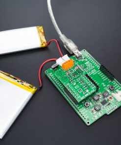
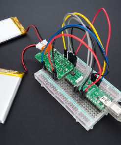
How does it work?
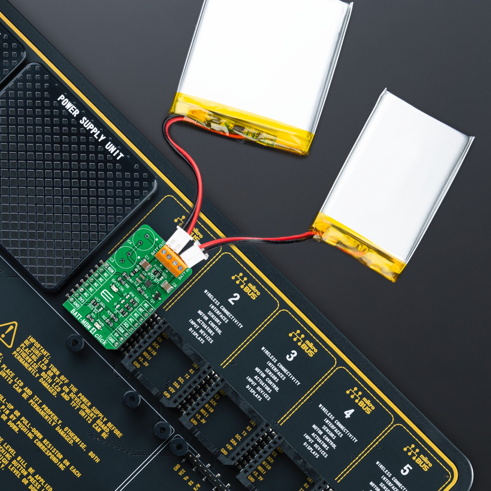
BATT-MON 4 Click as its foundation uses the LTC3337, a primary battery state of health monitor from Analog Devices, designed to be placed in series with a primary battery with minimal associated series voltage drop. The LTC3337 integrates a precision coulomb counter that monitors the accumulated charge transferred from a primary battery connected to its BATT IN terminal to an output load connected to its BATT OUT terminal. The patented infinite dynamic range coulomb counter tallies all accumulated battery discharge and stores it in an internal register accessible via an I2C interface.
This Click board™ communicates with MCU using the standard I2C 2-Wire interface to read data and configure settings, supporting Standard Mode operation with a clock frequency of 100kHz and Fast Mode up to 400kHz. The LTC3337 also integrates additional state of health monitoring, which measures and reports through the I2C interface, such as battery voltage, battery impedance, and temperature to quantify the battery’s charge state and health. In addition, it also has a programmable discharge alarm threshold based on this state of charge (SOC). An interrupt is generated at the INT pin of the mikroBUS™ socket when the threshold is reached.
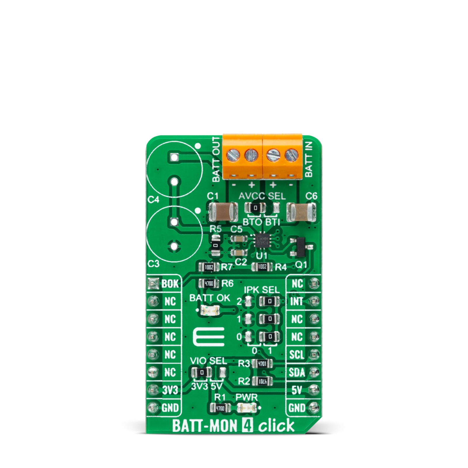
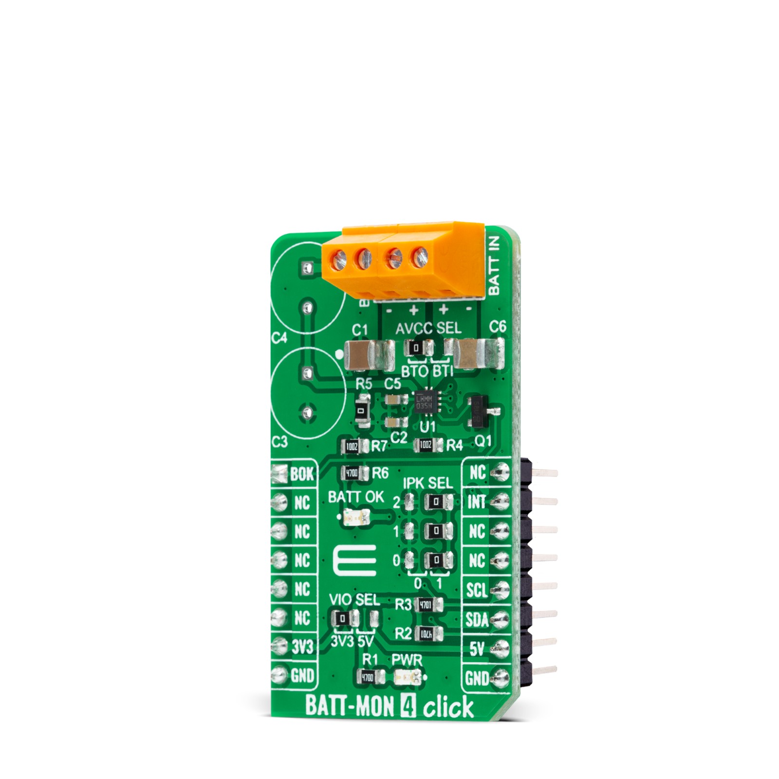
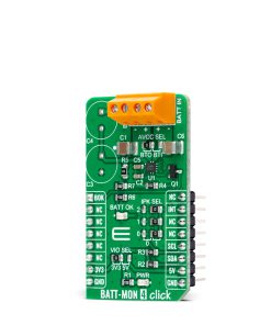
An integrated coulomb counter operates with a configurable peak current limit. The LTC3337 supports input voltages from 1.8V to 5.5V and a peak current up to 100mA; more precisely, the peak input current limit is selectable from 5mA to 100mA. The selection can be made by positioning SMD jumpers labeled as IPK SEL to an appropriate position 0 or 1.
Coulombs can be calculated for either the BATT IN or BATT OUT terminal, determined by the selected position of the AVCC SEL jumper. The AVCC SEL serves as the power supply for all internal LTC3337 circuits and can be connected to BATT IN or BATT OUT terminal. With AVCC connected to BATT OUT, the coulomb counter counts all coulombs coming out of the battery, including those associated with the LTC3337’s quiescent current, which effectively parallels the output load at BATT OUT. When connecting AVCC to BATT IN, the LTC3337’s quiescent current represents an error on coulombs out of the battery. However, coulombs associated purely with the output load are now more accurately counted, and this may be beneficial in output power metering applications.
BATT-MON 4 Click also possesses one green LED indicator labeled as BATT OK used as a battery status indicator, alongside the option of utilizing a stack of two supercapacitors, C4 and C3, an integrated ±10mA supercapacitor balancer available to balance a stack of two supercapacitors at the BATT OUT terminal. This option is turned off by default with capacitors C4 and C3 unpopulated and resistor R5 populated. To activate this feature, remove the R5 resistor and populate C4 and C3 capacitors (an example of capacitors used on this board is SCCR20B335PRB).
This Click board™ can operate with both 3.3V and 5V logic voltage levels selected via the VIO SEL jumper. This way, it is allowed for both 3.3V and 5V capable MCUs to use the communication lines properly. However, the Click board™ comes equipped with a library that contains easy-to-use functions and an example code that can be used, as a reference, for further development.
Specifications
Type
Battery charger
Applications
Can be used for primary battery-powered system applications, remote industrial sensor applications, or backup power supply applications
On-board modules
LTC3337 – primary battery state of health monitor from Analog Devices
Key Features
Low power consumption, built-in precision coulomb counter, designed to be placed in series with a primary battery, state-of-health monitor for primary battery, integrated supercapacitor balancer, programmable current limit, and more
Interface
I2C
Feature
No ClickID
Compatibility
mikroBUS™
Click board size
M (42.9 x 25.4 mm)
Input Voltage
3.3V or 5V,External
Pinout diagram
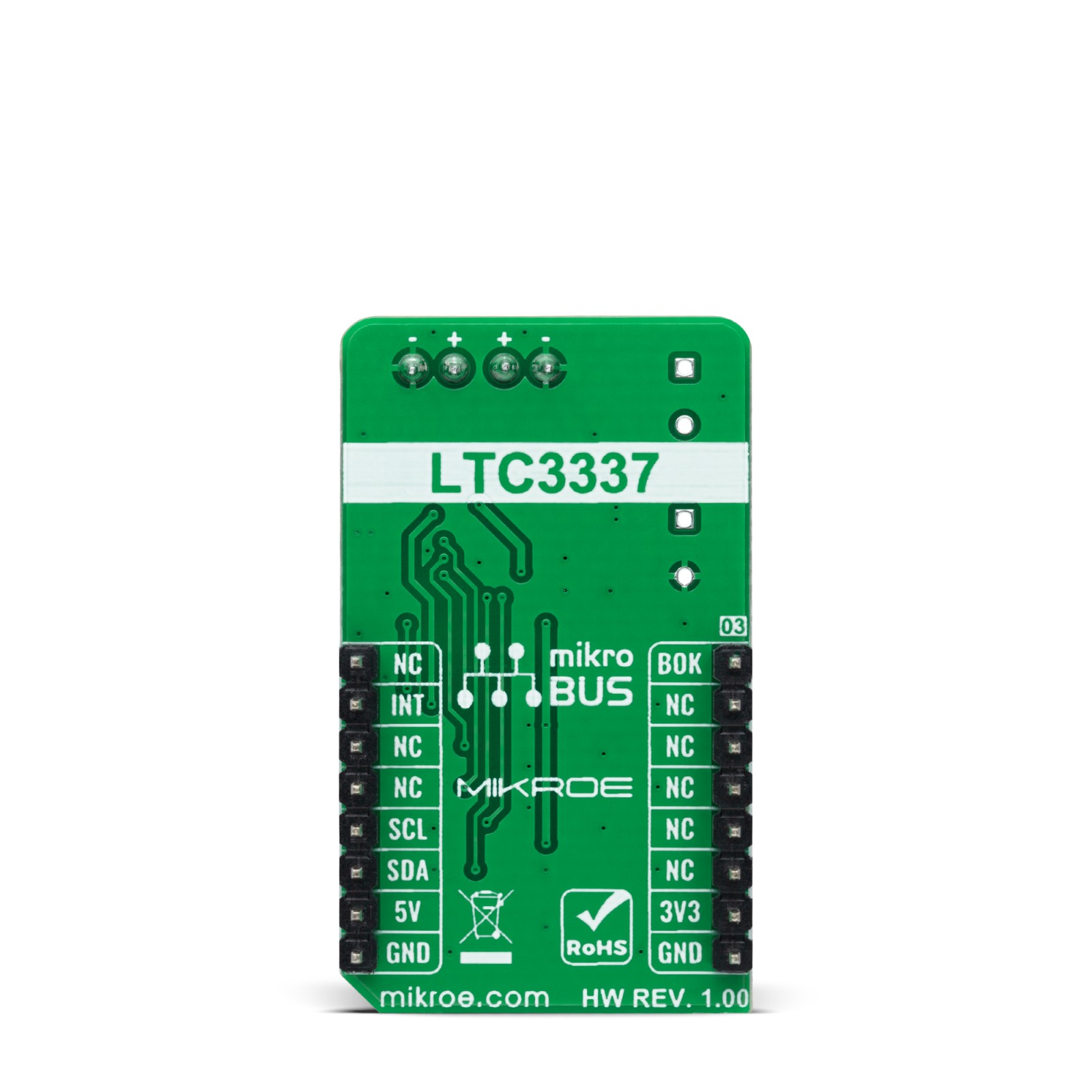
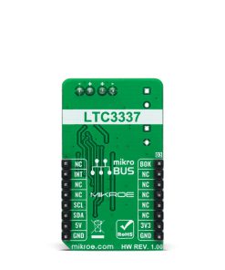
This table shows how the pinout on BATT-MON 4 Click corresponds to the pinout on the mikroBUS™ socket (the latter shown in the two middle columns).
Onboard settings and indicators
Label | Name | Default | Description |
---|---|---|---|
LD1 | PWR | – | Power LED Indicator |
LD2 | BATT OK | – | Battery Status LED Indicator |
JP1 | VIO SEL | Left | Logic Level Voltage Selection 3V3/5V: Left position 3V3, Right position 5V |
JP2 | AVCC SEL | Left | LTC3337 Power Supply Selection BTO/BTI: Left position BTO, Right position BTI |
JP3-JP5 | IPK SEL | Right | Input Current Limit Selection 0/1: Left position 0, Right position 1 |
R5 | R5 | Populated | Supercapacitor Balancer Activation Jumper |
BATT-MON 4 Click electrical specifications
Description | Min | Typ | Max | Unit |
---|---|---|---|---|
Supply Voltage VCC | 3.3 | – | 5 | V |
External Supply Voltage | 1.8 | – | 5.5 | V |
Current Limit Range | 5 | – | 100 | mA |
Operating Temperature Range | -40 | +25 | +120 | °C |
Software Support
We provide a library for the BATT-MON 4 Click as well as a demo application (example), developed using MikroElektronika compilers. The demo can run on all the main MikroElektronika development boards.
Package can be downloaded/installed directly from NECTO Studio Package Manager(recommended way), downloaded from our LibStock™ or found on Mikroe github account.
Library Description
This library contains API for BATT-MON 4 Click driver.
Key functions
-
battmon4_get_die_temperature
This function reads the chip DIE temperature in Celsius. -
battmon4_get_batt_in_voltage
This function reads the voltage from BATT IN when Ipeak is ON and OFF. -
battmon4_get_batt_out_voltage
This function reads the voltage from BATT OUT when Ipeak is ON and OFF.
Example Description
This example demonstrates the use of BATT-MON 4 Click board™ by reading the battery voltage and the chip internal temperature.
void application_task ( void )
{
float die_temperature, batt_in_v_ipeak_on, batt_in_v_ipeak_off, batt_out_v_ipeak_on, batt_out_v_ipeak_off;
if ( BATTMON4_OK == battmon4_get_die_temperature ( &battmon4, &die_temperature ) )
{
log_printf ( &logger, " Die Temperature: %.2f C rnn", die_temperature );
}
if ( BATTMON4_OK == battmon4_get_batt_in_voltage ( &battmon4, &batt_in_v_ipeak_on, &batt_in_v_ipeak_off ) )
{
log_printf ( &logger, " BATT IN rn Ipeak ON: %.1f mV rn Ipeak OFF: %.1f mV rnn",
batt_in_v_ipeak_on, batt_in_v_ipeak_off );
}
if ( BATTMON4_OK == battmon4_get_batt_out_voltage ( &battmon4, &batt_out_v_ipeak_on, &batt_out_v_ipeak_off ) )
{
log_printf ( &logger, " BATT OUT rn Ipeak ON: %.1f mV rn Ipeak OFF: %.1f mV rnn",
batt_out_v_ipeak_on, batt_out_v_ipeak_off );
}
Delay_ms ( 1000 );
}
The full application code, and ready to use projects can be installed directly from NECTO Studio Package Manager(recommended way), downloaded from our LibStock™ or found on Mikroe github account.
Other Mikroe Libraries used in the example:
- MikroSDK.Board
- MikroSDK.Log
- Click.BATTMON4
Additional notes and informations
Depending on the development board you are using, you may need USB UART click, USB UART 2 Click or RS232 Click to connect to your PC, for development systems with no UART to USB interface available on the board. UART terminal is available in all MikroElektronika compilers.
mikroSDK
This Click board™ is supported with mikroSDK – MikroElektronika Software Development Kit. To ensure proper operation of mikroSDK compliant Click board™ demo applications, mikroSDK should be downloaded from the LibStock and installed for the compiler you are using.
For more information about mikroSDK, visit the official page.