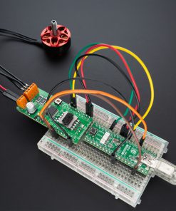
How does it work?
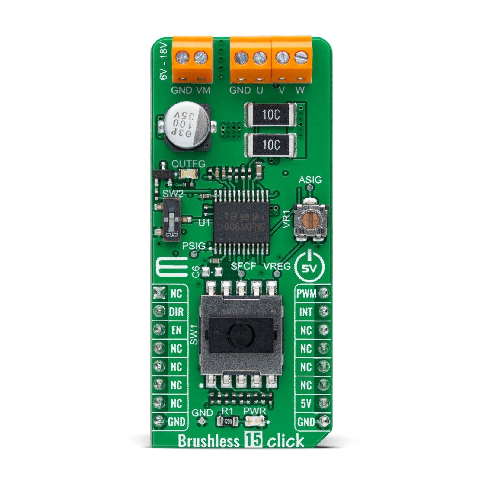
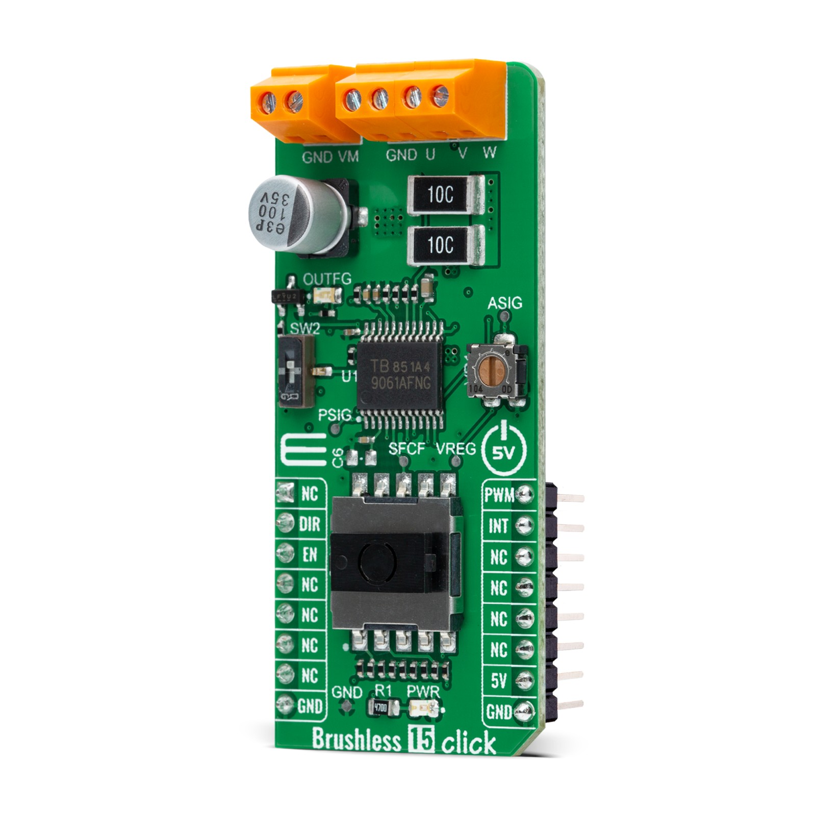
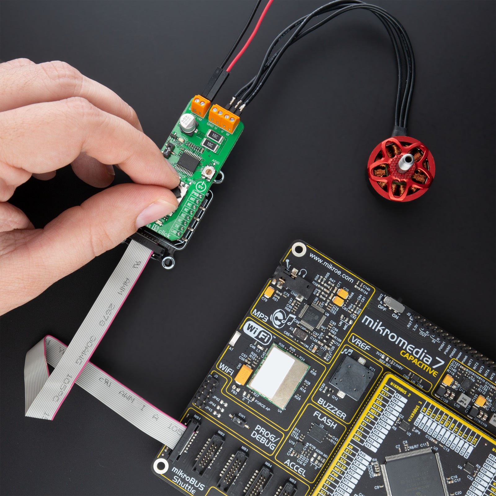
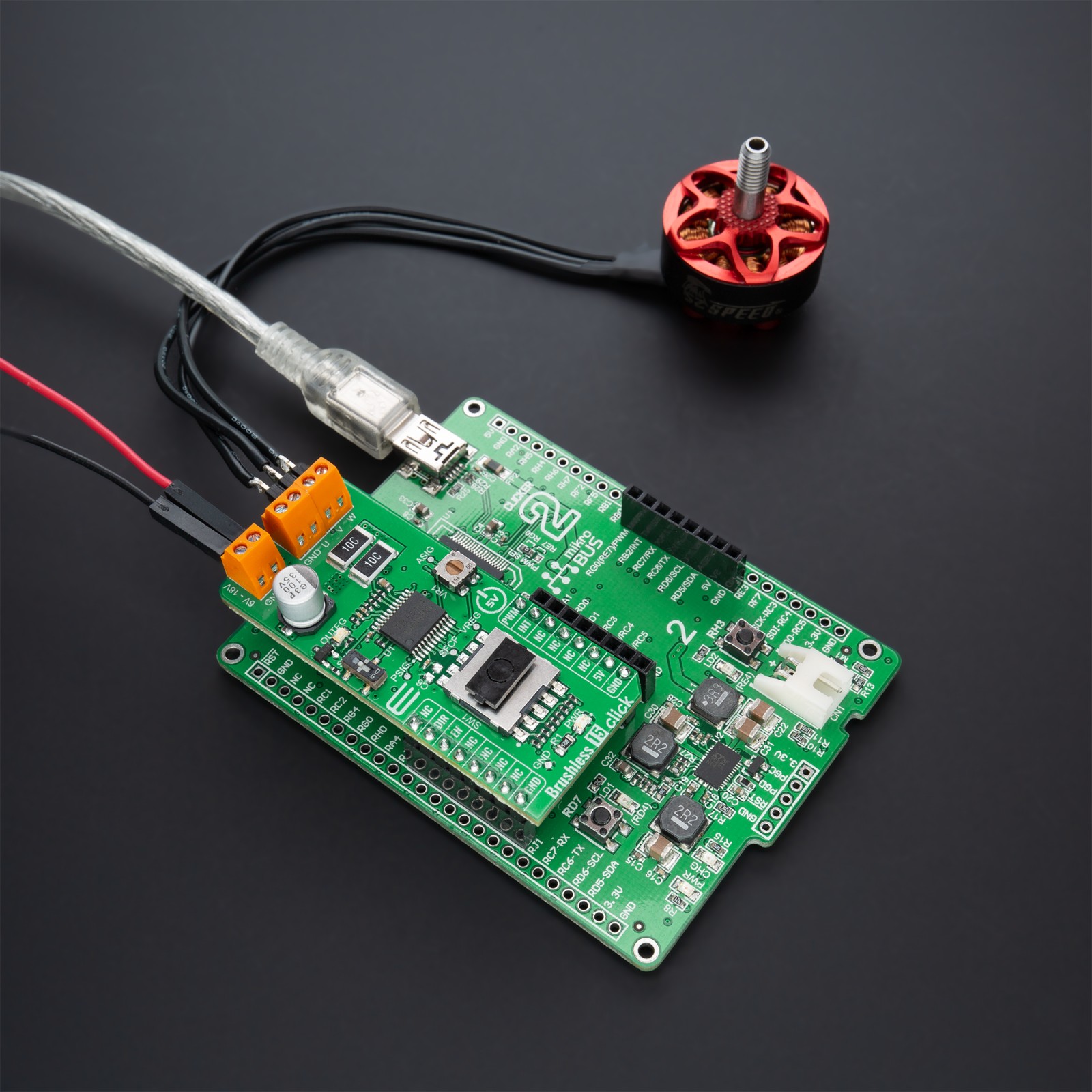
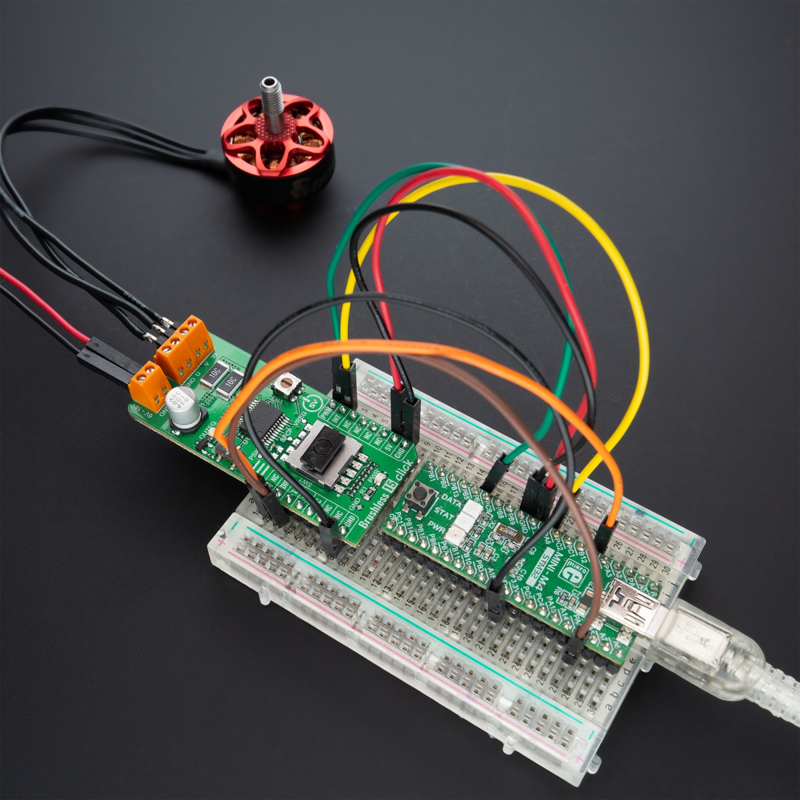
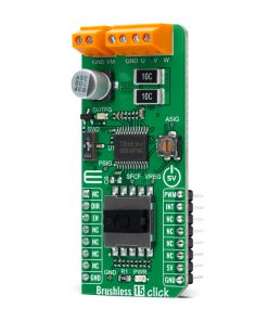
Brushless 15 Click as its foundation uses the TB9061AFNG, an automotive pre-driver that incorporates a sensorless controller for driving a 3-phase full-wave brushless DC motor from Toshiba Semiconductor. A 3-phase motor is driven by the PWM output signals, with the duty cycle determined by the PWM signal from mikroBUS. This input PWM signal is measured, calculated, and corrected in the logic circuit. The TB9061AFNG generates a 20kHz internal PWM signal according to its result. After that, the TB9061AFNG inputs internal PWM into the Sensorless Core Logic and outputs a sensorless driving signal for a 3-phase brushless motor.
In addition to the PWM signal, the internal PWM duty cycle can also be controlled using an analog voltage applied to the ASIG pin of the TB9061AFNG, set manually using an onboard trimmer labeled as VR1. Analog voltage from the VR1 controls the internal PWM duty cycle when the PWM pin is shorted to the ground. The user can also select a forced commutation frequency by choosing the input voltage via an onboard rotary switch labeled as SW1. Using an SW1, the TB9061AFNG receives the voltage at the SFCF (forced commutation frequency select) pin through the internal ADC and decides the forced commutation frequency from 9.375 up to 25.000rpm.
The user can also set a lead angle value at 7.5, 15, or 30° according to the setting of the SW2 switch. When SW2 is in a lower position, a lead angle is set to 7.5°, the upper position represents a lead angle of 15° set, and the middle position matches a lead angle of 30°. If 7.5 or 15° is selected, the lead angle is set to 0° during the forced commutation. When the normal commutation is started, it is changed automatically to the value specified by the SW2. If 30° is selected, the lead angle is set to 30 ° even during the forced commutation.
The TB9061AFNG features several diagnostic circuits and drive control functions, including over-current detection and a motor drive current limiter circuit, over-temperature (both internal and external), and over-voltage detection. Motor lock detection, step-out detection, and automatic return control circuits are also incorporated.
Alongside the PWM pin from the mikroBUS™ socket, used to drive a 3-phase motor, this Click board™ also has the Enable pin labeled as EN and routed to the CS pin of the mikroBUS™ socket to optimize power consumption used for power ON/OFF purposes (performs Start and Stop controls of the motor operation). The DIR pin, routed on the RST pin of the mikroBUS™ socket, is used to select the direction of motor rotation (clockwise/counterclockwise). Besides, it is possible to detect a rotation speed and irregular operations, such as motor lock-up, where the indication of such a condition is performed using the blue LED indicator labeled as OUTFG routed on the INT pin of the mikroBUS™ socket.
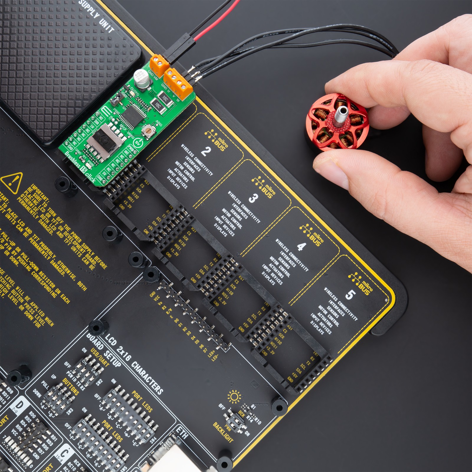
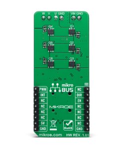
This Click board™ supports an external power supply for the motor, which can be connected to the input terminal labeled as VM and should be within the range of 6V to 18V, while the BLDC motor coils can be connected to the terminals labeled as U, V, and W.
This Click board™ can be operated only with a 5V logic voltage level. Therefore, the board must perform appropriate logic voltage level conversion before using MCUs with different logic levels. However, the Click board™ comes equipped with a library containing functions and an example code that can be used, as a reference, for further development.
Specifications
Type
Brushless
Applications
Can control motors without using heat-sensitive hole sensors, securing control of pumps in a hot environment providing optimum operating efficiency in automotive applications
On-board modules
TB9061AFNG – automotive pre-driver that incorporates a sensorless controller for driving a 3-phase full-wave brushless DC motor from Toshiba Semiconductor
Key Features
3-phase full-wave sensorless drive, compatible with both external PWM duty input and DC input control, lead angle control, rotation-speed and lock detection, protection features, and more.
Interface
GPIO,PWM
Feature
No ClickID
Compatibility
mikroBUS™
Click board size
L (57.15 x 25.4 mm)
Input Voltage
5V,External
Silicon Vendor
Toshiba Semi.
Pinout diagram
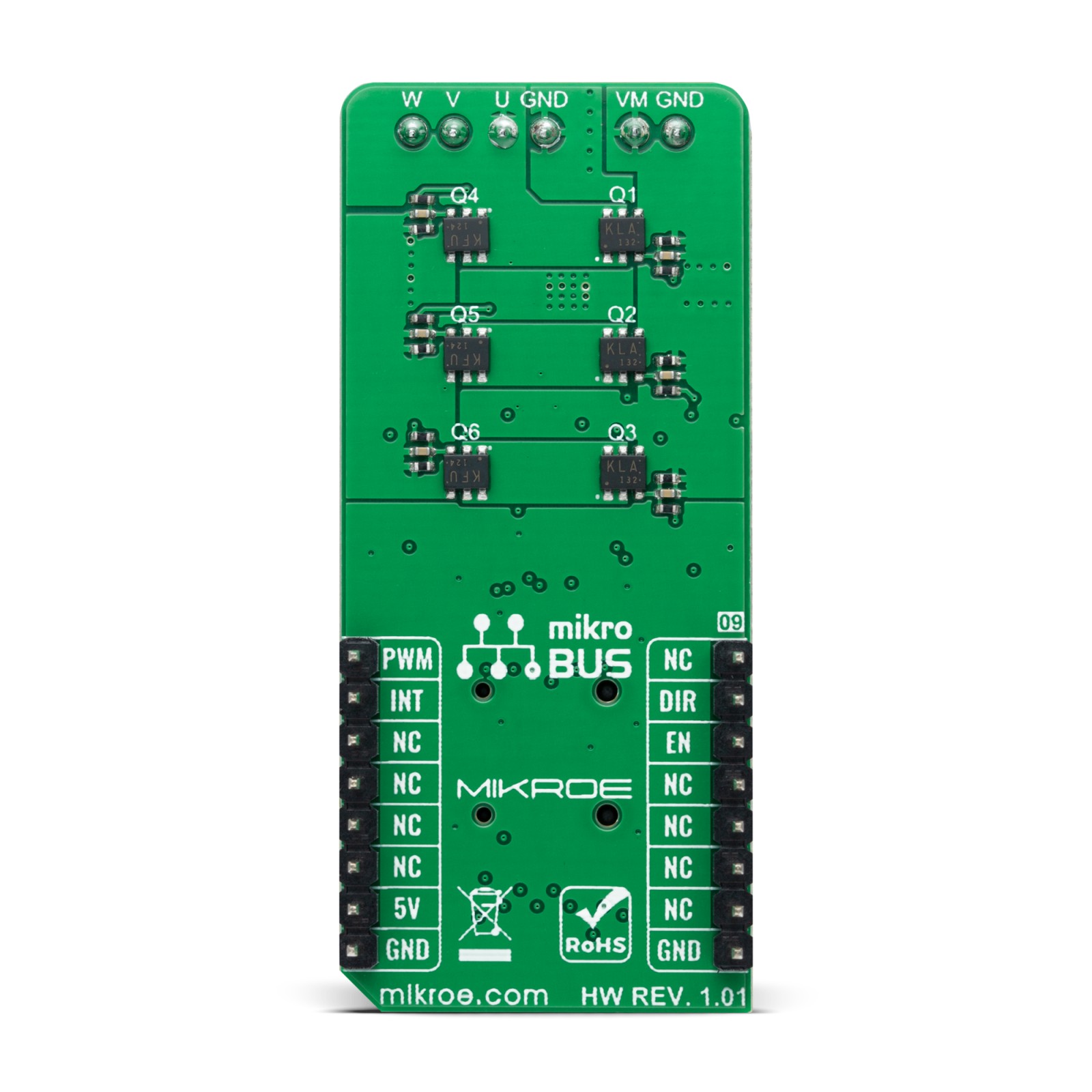
This table shows how the pinout on Brushless 15 Click corresponds to the pinout on the mikroBUS™ socket (the latter shown in the two middle columns).
Onboard settings and indicators
Label | Name | Default | Description |
---|---|---|---|
LD1 | PWR | – | Power LED Indicator |
LD2 | OUTFG | – | Rotation Speed/Irregular Operation LED Indicator |
SW1 | SW1 | – | Forced Commutation Frequency Selection 8-Position Switch (from 9.375 up to 25.000rpm) |
SW2 | SW2 | – | Lead Angle Selection Switch |
VR1 | VR1 | – | PWM Duty Cycle Control Trimmer |
Brushless 15 Click electrical specifications
Description | Min | Typ | Max | Unit |
---|---|---|---|---|
Supply Voltage VCC | – | 5 | – | V |
External Power Supply VM | 6 | – | 18 | V |
Maximum Output Current | – | – | 20 | mA |
Operating Temperature Range | -40 | +25 | +125 | °C |
Software Support
We provide a library for the Brushless 15 Click as well as a demo application (example), developed using MikroElektronika compilers. The demo can run on all the main MikroElektronika development boards.
Package can be downloaded/installed directly from NECTO Studio Package Manager(recommended way), downloaded from our LibStock™ or found on Mikroe github account.
Library Description
This library contains API for Brushless 15 Click driver.
Key functions
-
brushless15_set_duty_cycle
This function sets the PWM duty cycle in percentages ( Range[ 0..1 ] ). -
brushless15_enable_device
This function enables the device by setting the EN pin to low logic state. -
brushless15_switch_direction
This function switches the direction by toggling the DIR pin state.
Example Description
This example demonstrates the use of the Brushless 15 Click board™ by driving the motor in both directions at different speeds.
void application_task ( void )
{
static int8_t duty_cnt = 2;
static int8_t duty_inc = 1;
float duty = duty_cnt / 10.0;
brushless15_set_duty_cycle ( &brushless15, duty );
log_printf( &logger, "> Duty: %d%%rn", ( uint16_t )( duty_cnt * 10 ) );
Delay_ms( 1000 );
duty_cnt += duty_inc;
if ( 8 == duty_cnt )
{
duty_inc = -1;
}
else if ( 1 == duty_cnt )
{
duty_inc = 1;
duty_cnt = 2;
log_printf( &logger, " Switch directionrnn" );
brushless15_switch_direction ( &brushless15 );
}
}
The full application code, and ready to use projects can be installed directly from NECTO Studio Package Manager(recommended way), downloaded from our LibStock™ or found on Mikroe github account.
Other Mikroe Libraries used in the example:
- MikroSDK.Board
- MikroSDK.Log
- Click.Brushless15
Additional notes and informations
Depending on the development board you are using, you may need USB UART click, USB UART 2 Click or RS232 Click to connect to your PC, for development systems with no UART to USB interface available on the board. UART terminal is available in all MikroElektronika compilers.
mikroSDK
This Click board™ is supported with mikroSDK – MikroElektronika Software Development Kit. To ensure proper operation of mikroSDK compliant Click board™ demo applications, mikroSDK should be downloaded from the LibStock and installed for the compiler you are using.
For more information about mikroSDK, visit the official page.