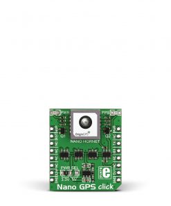
IRNSS Click
R735.00 ex. VAT
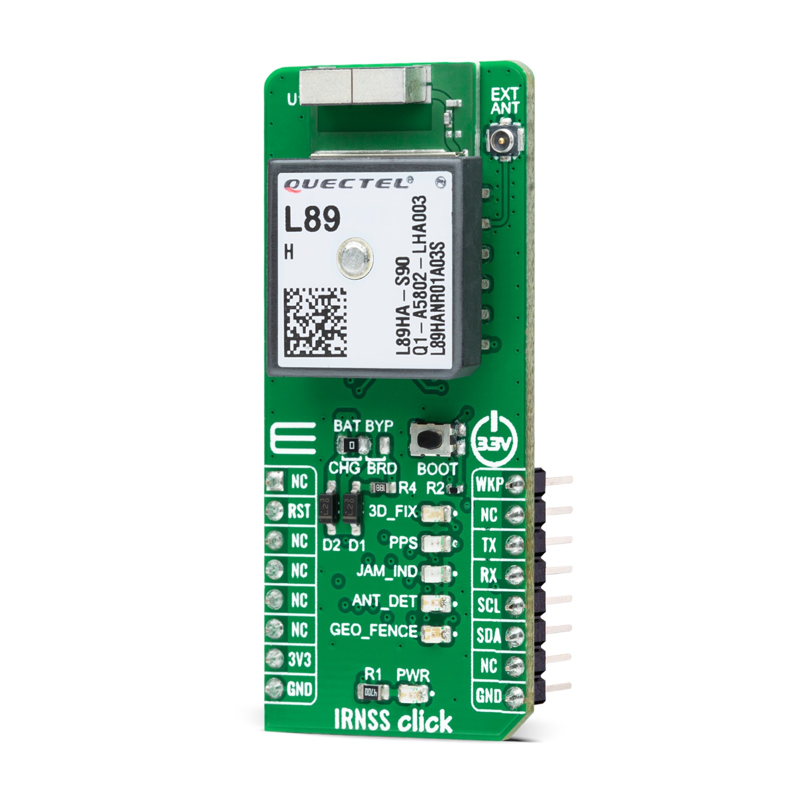
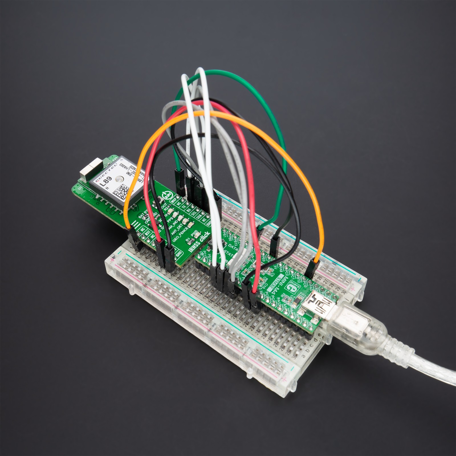
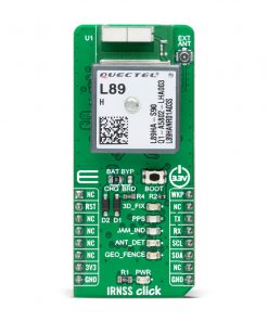
IRNSS Click is a compact add-on board that provides fast positioning capability. This board features the L89H, a high-performance IRNSS-enabled GNSS module capable of acquiring and tracking GPS, IRNSS, GLONASS, BeiDou, Galileo, and QZSS signals from Quectel Wireless Solutions. The module can work at L1 and L5 bands with two embedded antennas simultaneously with a default configuration of GPS+Galileo+IRNSS. Compared with the GNSS module that works at the L1 band only, the L89H uses signals in default configuration to increase the number of visible satellites, reduce TTFF and enhance positioning accuracy, mainly when is used in rough urban environments. This Click board™ is suitable for both acquisition and tracking and represents an ideal product for automotive, consumer, and industrial tracking applications.
IRNSS Click is supported by a mikroSDK compliant library, which includes functions that simplify software development. This Click board™ comes as a fully tested product, ready to be used on a system equipped with the mikroBUS™ socket.
Stock: Lead-time applicable.
| 5+ | R698.25 |
| 10+ | R661.50 |
| 15+ | R624.75 |
| 20+ | R601.23 |
How does it work?
IRNSS Click as its foundation uses the L89H, a high-performance acquiring and tracking IRNSS-enabled GNSS module from Quectel Wireless Solutions. It achieves a high industrial level of sensitivity, accuracy, and TTFF with low power consumption. The embedded flash memory provides a capacity for storing user-specific configurations and allows for future updates. It is fully compliant with the EU RoHS directive supporting multiple positioning and navigation systems, including autonomous GPS, BeiDou, GLONASS, Galileo, IRNSS, SBAS (including WAAS, EGNOS, MSAS, and GAGAN), QZSS, DGPS, and AGPS.

IRNSS Click provides the possibility of using both UART and I2C interfaces. The UART interface supports data baud-rate from 4800bps to 921600bps, with 921600bps by default, while the I2C interface supports a fast mode of operation with a bit rate up to 400kbps. Alongside interface pins, this Click board™ also has a Reset feature routed to the RST pin on the mikroBUS™ socket, which with a low logic level, puts the module into a Reset state, and with a high level operates module normally. And with that, it also has a Wake-Up feature, routed to the PWM pin on the mikroBUS™ socket, which will force the module to wakes up from Backup mode.
This Click board™ uses five different LED indicators available for signal indication:
- Blue LED labeled as 3D_FIX turns on to indicate successful positioning after the L89H module is turned on
- Yellow LED labeled as PPS indicates one pulse per second synchronized to GNSS satellites. Keep in mind that PPS can be held even after losing the satellite signal by the internal RTC.
- Red LED labeled as JAM_IND represents a jamming detection indicator to detect whether any jammers may have an impact on the module
- Green LED labeled as ANT_DET indicates active antenna status – Orange LED labeled as GEO_FENCE indicates whether the module enters or exits the geo-fence
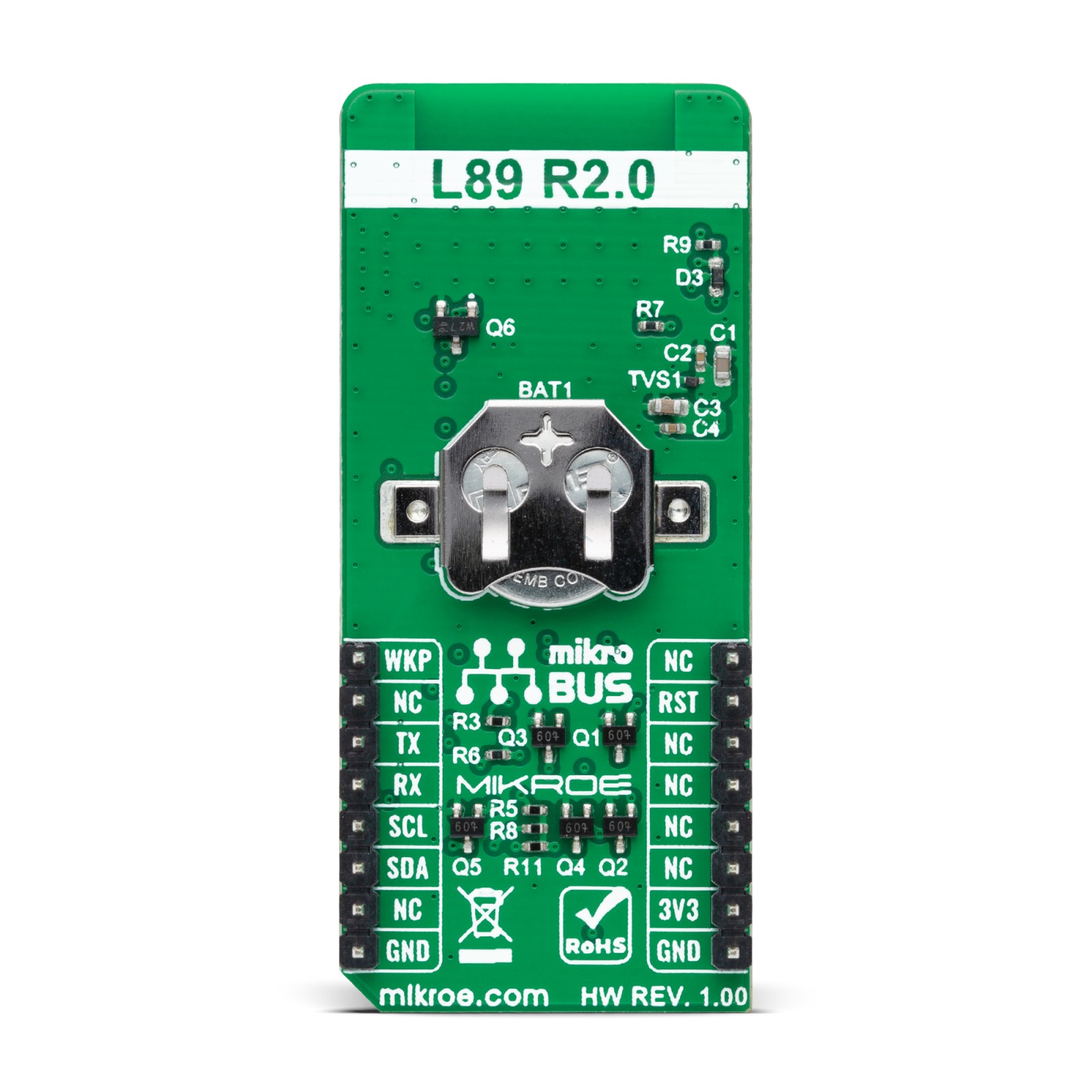
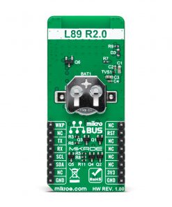
In the primary power supply failure case, the module can use a backup supply voltage from a connected battery. IRNSS Click can use an externally chargeable battery from the button cell battery holder, suitable for 12mm Coin Cell batteries if the SMD jumper labeled as BAT BYP is positioned to a position marked as CHG for uninterrupted operation. Otherwise, when the jumper is in a position labeled as BRD, the module is powered only by 3.3V from the board, and if the jumper is not even populated, then the module is powered from a non-chargeable battery.
The L89H module can be connected to a dedicated passive or active GNSS antenna with a built-in LNA for sensitivity improvement. IRNSS Click possesses a miniature coaxial N.FL series antenna connector which, in combination with IPEX-SMA cable, allows connecting the appropriate antenna, such as GNSS Active External Antenna or other external antennas from our offer for improved range and received signal strength.
This Click board™ can be operated only with a 3.3V logic voltage level. The board must perform appropriate logic voltage level conversion before use with MCUs with different logic levels. However, the Click board™ comes equipped with a library containing functions and an example code that can be used, as a reference, for further development.
Specifications
Type
GPS/GNSS
Applications
Can be used for both acquisition and tracking and represents an ideal product for automotive, consumer, and industrial tracking applications
On-board modules
L89H – high-performance acquiring and tracking IRNSS-enabled GNSS module from Quectel Wireless Solutions
Key Features
Low power consumption, support IRNSS L5 band, external and chip antenna, multi-GNSS engines for GPS, IRNSS, GLONASS, BeiDou, Galileo and QZSS, integrated LNAs for better sensitivity, anti-jamming feature, and more
Interface
I2C,UART
Feature
No ClickID
Compatibility
mikroBUS™
Click board size
L (57.15 x 25.4 mm)
Input Voltage
3.3V
Pinout diagram
This table shows how the pinout on IRNSS Click corresponds to the pinout on the mikroBUS™ socket (the latter shown in the two middle columns).
Onboard settings and indicators
| Label | Name | Default | Description |
|---|---|---|---|
| LD1 | PWR | – | Power LED Indicator |
| LD2 | 3D_FIX | – | Successful Position LED Indicator |
| LD3 | PPS | – | Achieved 3D_FIX Position LED Indicator |
| LD4 | JAM_IND | – | Jamming LED Indicator |
| LD5 | ANT_DET | – | Active Antenna Status LED Indicator |
| LD6 | GEO_FENCE | – | Enter/Exit Geo-Fence LED Indicator |
| JP1 | BAT BYP | Left | Backup Power Supply Selection |
| T1 | BOOT | – | FW Update Boot Button |
IRNSS Click electrical specifications
| Description | Min | Typ | Max | Unit |
|---|---|---|---|---|
| Supply Voltage | – | 3.3 | – | V |
| Operating Frequency | 1.176 / 1.561 / 1.575 / 1.602 | GHz | ||
| Cold Start | – | <13 | – | sec |
| Acquisition Sensitivity | – | -147 | – | dBm |
| Tracking Sensitivity | – | -163 | – | dBm |
| Maximum Altitude Range | – | – | 18 | km |
| Operating Temperature Range | -40 | +25 | +85 | °C |
Software Support
We provide a library for the IRNSS Click as well as a demo application (example), developed using MikroElektronika compilers. The demo can run on all the main MikroElektronika development boards.
Package can be downloaded/installed directly from NECTO Studio Package Manager(recommended way), downloaded from our LibStock™ or found on mikroE github account.
Library Description
This library contains API for IRNSS Click driver.
Key functions:
void irnss_cfg_setup ( irnss_cfg_t *cfg );– Config Object Initialization function.IRNSS_RETVAL irnss_init ( irnss_t *ctx, irnss_cfg_t *cfg );– Initialization function.
Examples description
This example reads, processes and parses data from IRNSS clicks.
The application is composed of three sections :
void application_task ( void )
{
    irnss_process();


    err_t error_flag = irnss_element_parser( RSP_GNGGA, RSP_GNGGA_LATITUDE_ELEMENT,
                                             latitude_data );

    error_flag |= irnss_element_parser(  RSP_GNGGA, RSP_GNGGA_LONGITUDE_ELEMENT,
                                         longitude_data );

    error_flag |= irnss_element_parser(  RSP_GNGGA, RSP_GNGGA_ALTITUDE_ELEMENT,
                                         altitude_data );


    if ( error_flag == 0 )
    {
        if ( last_error_flag != 0)
        {
            log_printf( &logger, "rn" );
        }
        log_printf( &logger, ">Latitude:rn - deg: %.2s rn - min: %srn",
                    latitude_data, &latitude_data[ 2 ] );

        log_printf( &logger, ">Longitude:rn - deg: %.3s rn - min: %srn",
                    longitude_data, &longitude_data[ 3 ] );

        log_printf( &logger, ">Altitude:rn - %smrn",
                    altitude_data );

        log_printf( &logger, "----------------------------------------rn" );
    }
    else if ( error_flag < -1 )
    {
        if ( last_error_flag == 0 )
        {
            log_printf( &logger, "Waiting for data" );
        }
        log_printf( &logger, "." );
    }

    if ( error_flag != -1 )
    {
        last_error_flag = error_flag;
        irnss_clear_app_buf(  );
    }
}
The full application code, and ready to use projects can be installed directly from NECTO Studio Package Manager(recommended way), downloaded from our LibStock™ or found on mikroE github account.
Other mikroE Libraries used in the example:
- MikroSDK.Board
- MikroSDK.Log
- Click.IRNSS
Additional notes and informations
Depending on the development board you are using, you may need USB UART click, USB UART 2 click or RS232 click to connect to your PC, for development systems with no UART to USB interface available on the board. The terminal available in all MikroElektronika compilers, or any other terminal application of your choice, can be used to read the message.
mikroSDK
This Click board™ is supported with mikroSDK – MikroElektronika Software Development Kit. To ensure proper operation of mikroSDK compliant Click board™ demo applications, mikroSDK should be downloaded from the LibStock and installed for the compiler you are using.
For more information about mikroSDK, visit the official page.
Resources
Downloads
| Weight | 28 g |
|---|---|
| Brand | MikroElektronika |


