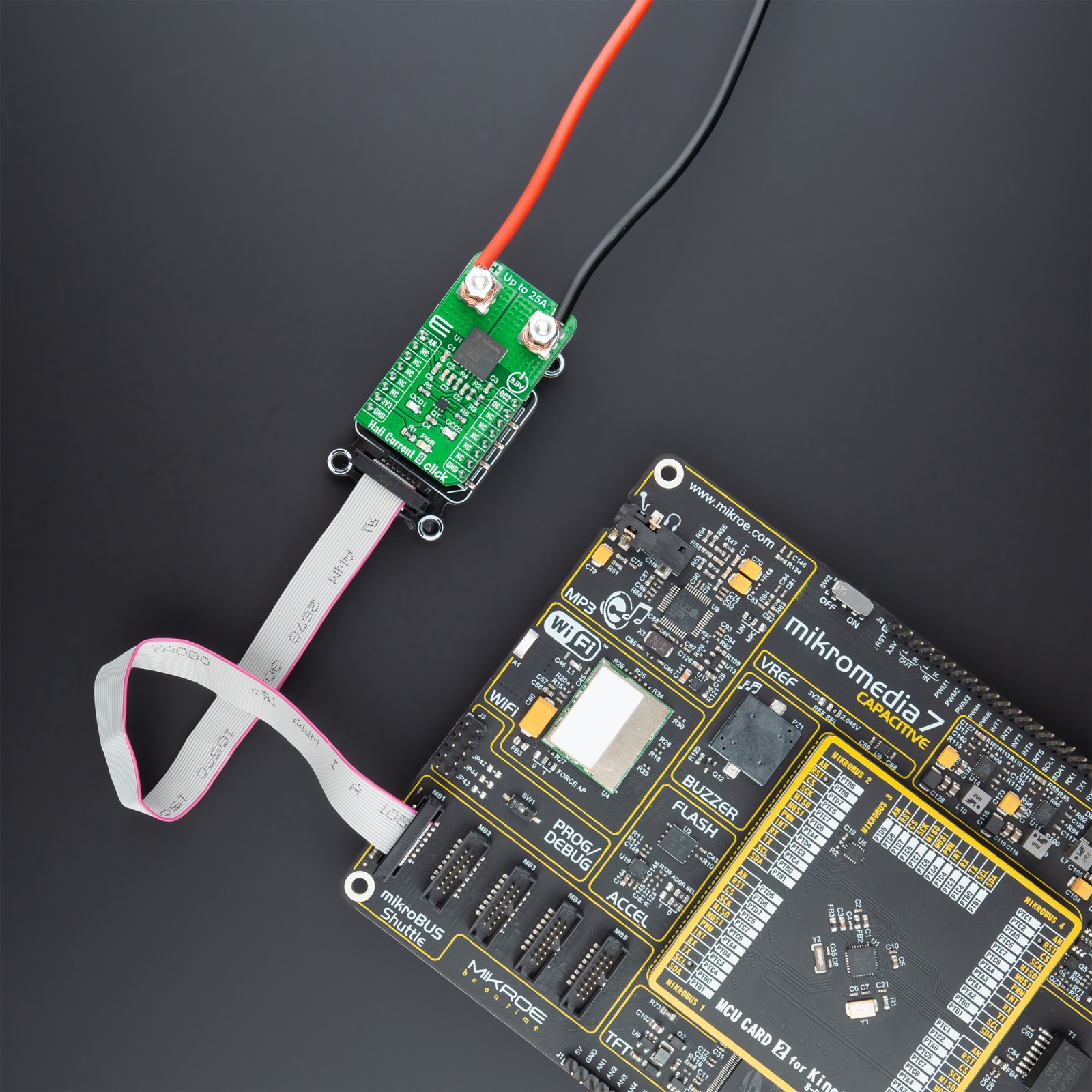
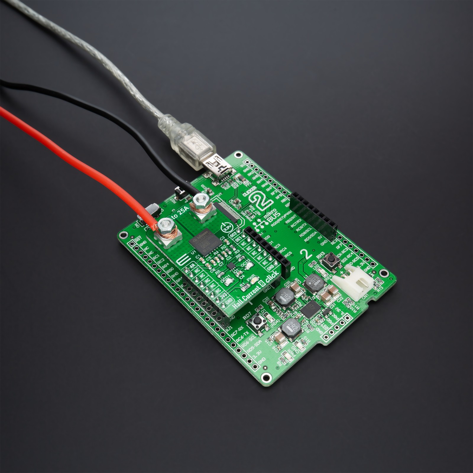
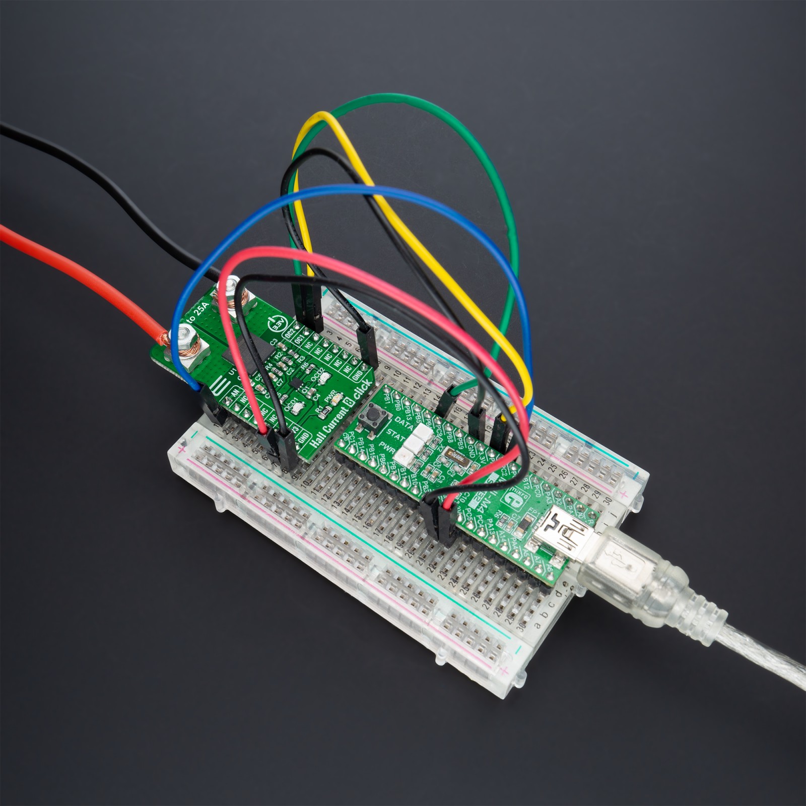
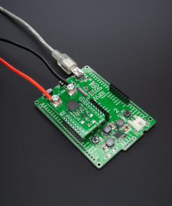
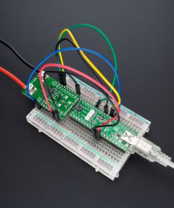
DO NOT TOUCH THE BOARD WHILE THE EXTERNAL POWER SUPPLY IS ON!
Note: Hall current click has exposed pins/pads. To stay safe take precaution when applying high voltage to the click. The click is to be used by trained personnel only when applying high voltage.
How does it work?
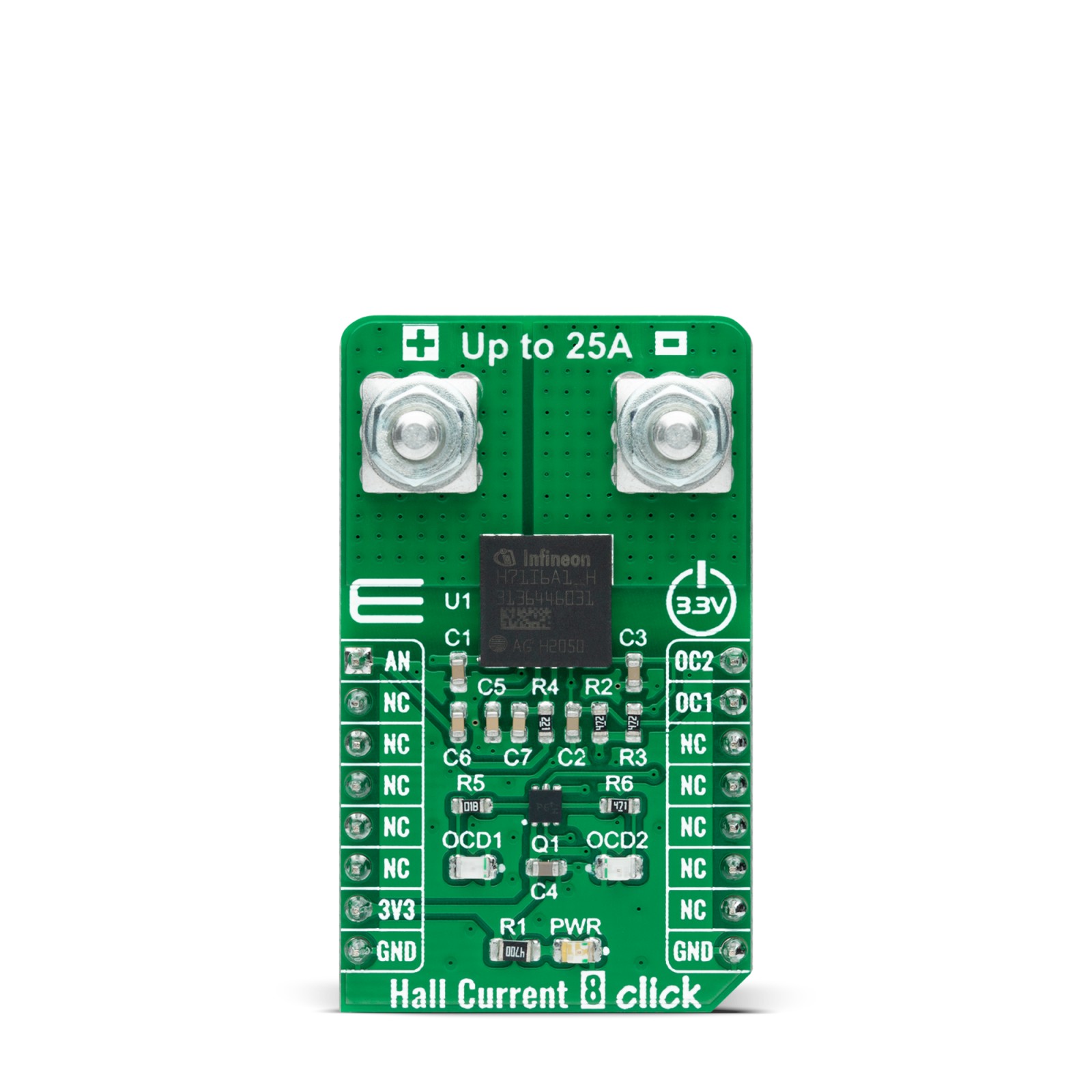
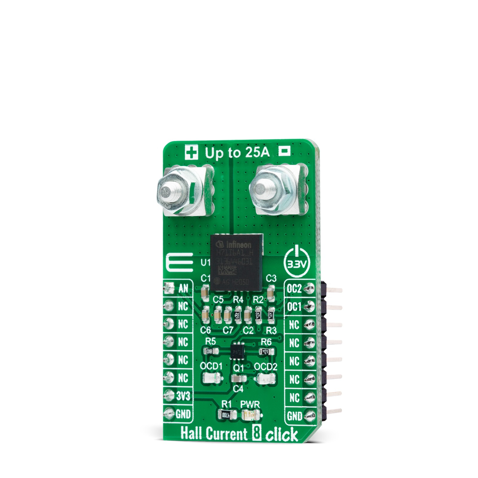
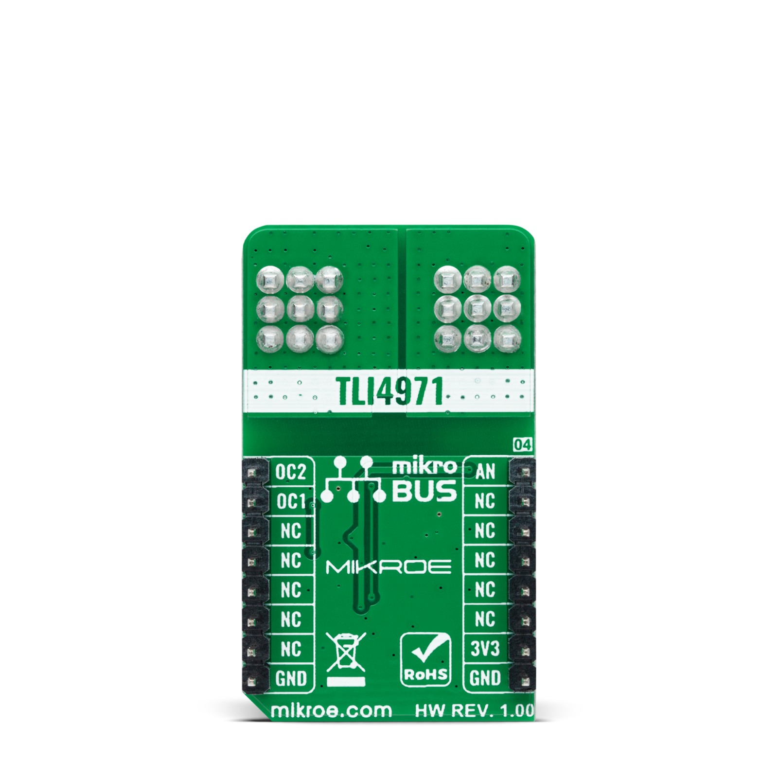
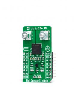
Hall Current 8 Click as its foundation uses the TLI4971-A025T5, a high-precision miniature coreless magnetic current sensor for AC and DC measurements with an analog interface and two fast overcurrent detection outputs from Infineon Technologies. The well-established Hall technology, on which the TLI4971 is based, enables accurate and highly linear measurement of currents with a full scale that depends on the chosen product variant, in this case, up to 25A. Typical applications are electrical drives and general-purpose inverters. It is suitable for fast over-current detection, which allows the control unit to switch off and protect the affected system from damage, independently from the primary measurement path.
The preconfigured output mode of the TLI4971-A025T5 is set to semi-differential mode. Current flowing through the primary conductors are galvanically isolated, protecting low-voltage parts of the Click board™, as well as the host MCU, and induces a magnetic field that is differentially measured by two Hall probes. A high-performance amplifier combines the signal resulting from the differential field and the internal compensation information provided by the temperature and stress compensation unit. Then the amplifier output signal is fed into a differential output amplifier, which drives the sensor’s analog output available on the AN pin of the mikroBUS™ socket.
In addition to the already mentioned characteristics, this Click board™ also has two separate interface pins (OCD), routed to the PWM and INT pins of the mikroBUS socket. They provide fast output signals if a current exceeds a preset threshold in combination with the red and yellow LEDs marked with OCD1 and OCD2. Those pins offer a swift response, thanks to independence from the main signal path. They can be used as a trap functionality to quickly shut down the current source and precisely detect mild overload conditions.
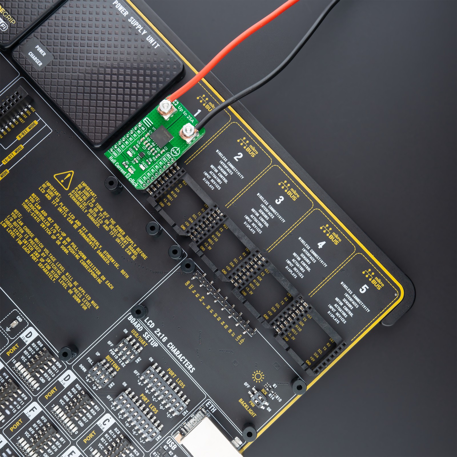
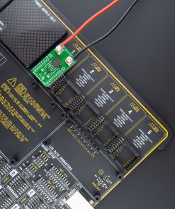
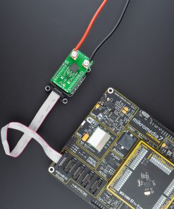
Also, this Click board™ should be connected in series with the load. The current is measured by two onboard terminal connectors, one terminal block for the positive and the other for the negative current input.
This Click board™ can be operated only with a 3.3V logic voltage level. The board must perform appropriate logic voltage level conversion before use with MCUs with different logic levels. However, the Click board™ comes equipped with a library containing functions and an example code that can be used, as a reference, for further development.
Specifications
Type
Current sensor,Measurements
Applications
Can be used for AC/DC current measurement applications: electrical drives, general-purpose inverters, chargers, current monitoring, overload, over-current detection, and many more.
On-board modules
TLI4971-A025T5 – high-precision miniature coreless magnetic current sensor for AC and DC measurements up to 25A with an analog interface and two fast overcurrent detection outputs from Infineon Technologies
Key Features
High accurate, scalable, DC & AC current sensing, analog interface and two independent fast Over-Current Detection (OCD) outputs, very low sensitivity error over temperature, and more.
Interface
Analog
Feature
No ClickID
Compatibility
mikroBUS™
Click board size
M (42.9 x 25.4 mm)
Input Voltage
3.3V
Pinout diagram
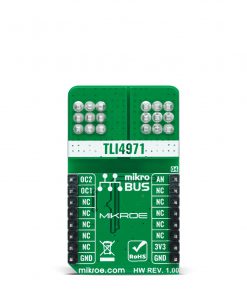
This table shows how the pinout on Hall Current 8 Click – 25A corresponds to the pinout on the mikroBUS™ socket (the latter shown in the two middle columns).
Onboard settings and indicators
Label | Name | Default | Description |
---|---|---|---|
LD1 | PWR | – | Power LED Indicator |
LD2 | OCD1 | – | Output 1 Overcurrent LED Indicator |
LD3 | OCD2 | – | Output 2 Overcurrent LED Indicator |
Hall Current 8 Click – 25A electrical specifications
Description | Min | Typ | Max | Unit |
---|---|---|---|---|
Supply Voltage | – | 3.3 | – | V |
Measurement Range | – | – | 25 | A |
Operating Temperature Range | -40 | +25 | +105 | °C |
Software Support
We provide a library for the Hall Current 8 Click as well as a demo application (example), developed using MikroElektronika compilers. The demo can run on all the main MikroElektronika development boards.
Package can be downloaded/installed directly from NECTO Studio Package Manager(recommended way), downloaded from our LibStock™ or found on mikroE github account.
Library Description
This library contains API for Hall Current 8 Click driver.
Key functions:
hallcurrent8_cfg_setup
– Config Object Initialization function.hallcurrent8_init
– Initialization function.hallcurrent8_default_cfg
– Click Default Configuration function.
Examples description
This library contains API for Hall Current 8 Click driver. The library initializes and defines the ADC drivers. The library also includes a function for calibration, current measurement and overcurrent detection.
The demo application is composed of two sections :
void application_task ( void ) { float hallcurrent8_current = 0; if ( hallcurrent8_get_current ( &hallcurrent8, &offset_val, &hallcurrent8_current ) != ADC_ERROR ) { log_printf( &logger, " Current : %.2f [A]rn", hallcurrent8_current ); } uint16_t hallcurrent8_an_value = 0; if ( hallcurrent8_read_an_pin_value ( &hallcurrent8, &hallcurrent8_an_value ) != ADC_ERROR ) { log_printf( &logger, " ADC Value : %urn", hallcurrent8_an_value ); } float hallcurrent8_an_voltage = 0; if ( hallcurrent8_read_an_pin_voltage ( &hallcurrent8, &hallcurrent8_an_voltage ) != ADC_ERROR ) { log_printf( &logger, " AN Voltage : %.2f [V]rn", hallcurrent8_an_voltage ); } log_printf( &logger, "---------------------------rn"); Delay_ms( 1000 ); }
The full application code, and ready to use projects can be installed directly from NECTO Studio Package Manager(recommended way), downloaded from our LibStock™ or found on mikroE github account.
Other mikroE Libraries used in the example:
- MikroSDK.Board
- MikroSDK.Log
- Click.HallCurrent8
Additional notes and informations
Depending on the development board you are using, you may need USB UART click, USB UART 2 click or RS232 click to connect to your PC, for development systems with no UART to USB interface available on the board. The terminal available in all MikroElektronika compilers, or any other terminal application of your choice, can be used to read the message.
mikroSDK
This Click board™ is supported with mikroSDK – MikroElektronika Software Development Kit. To ensure proper operation of mikroSDK compliant Click board™ demo applications, mikroSDK should be downloaded from the LibStock and installed for the compiler you are using.
For more information about mikroSDK, visit the official page.