BLE TINY Click
R315.00 ex. VAT
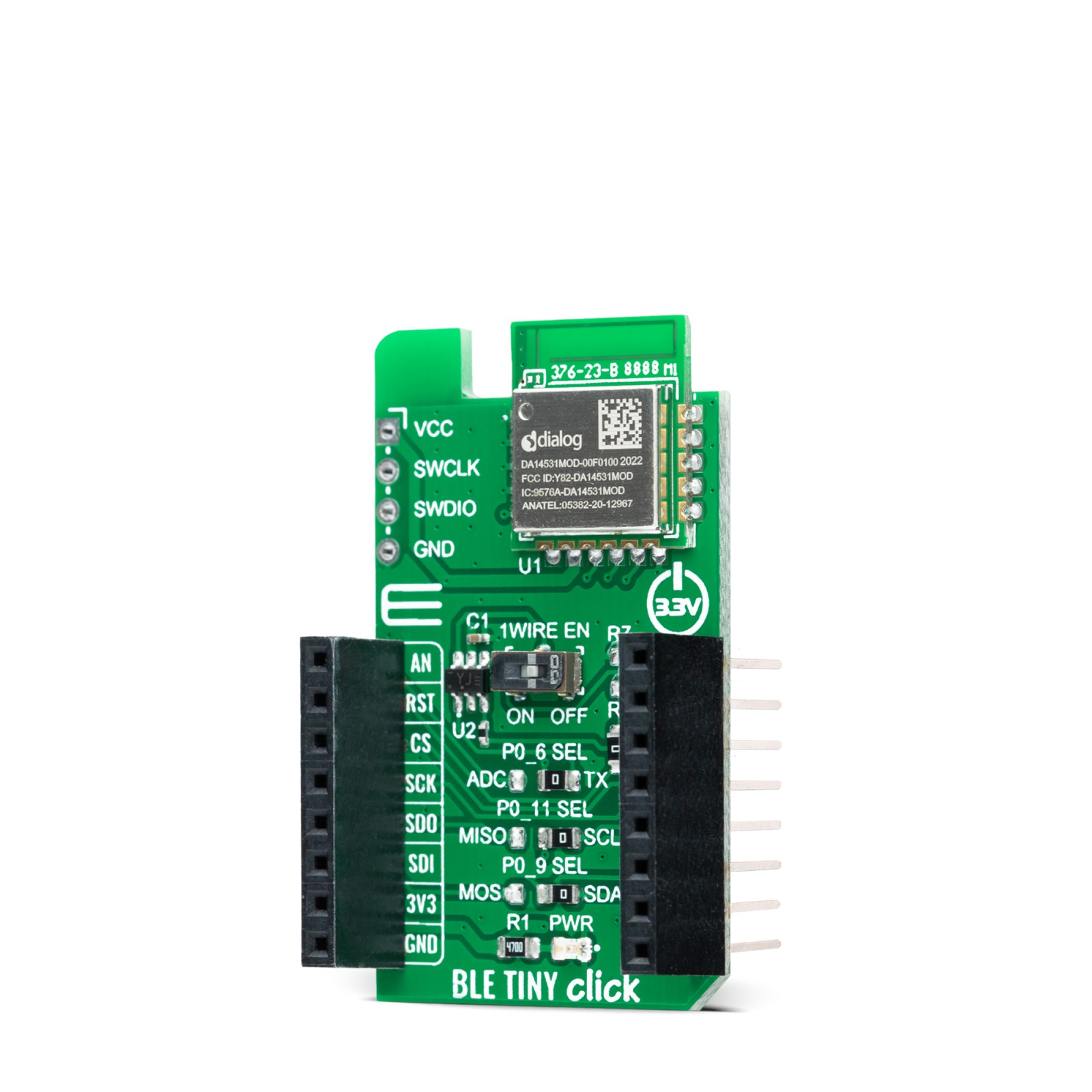
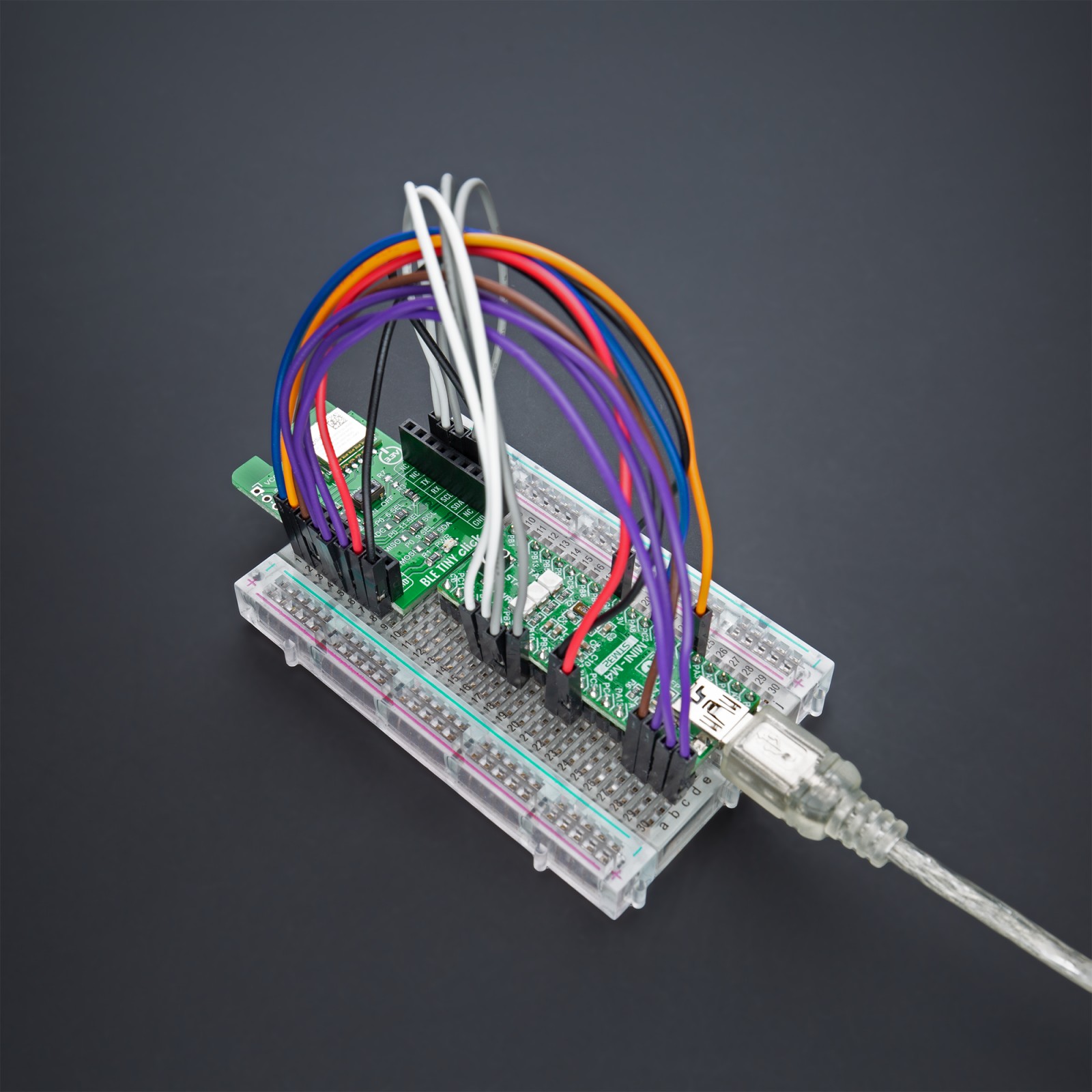
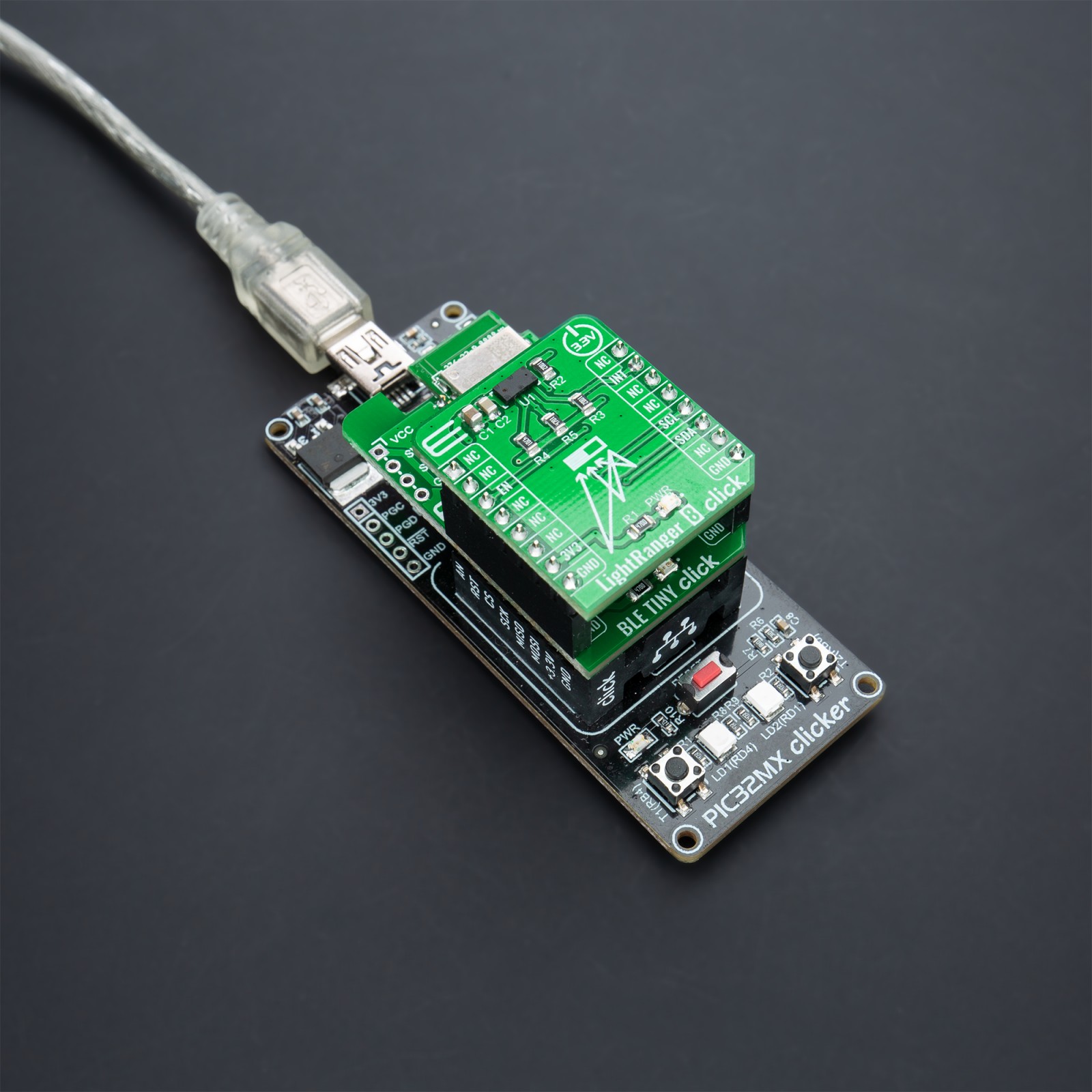
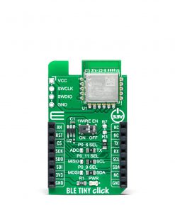
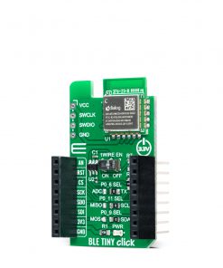
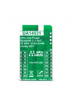
BLE TINY Click is a compact add-on board that provides BLE connectivity for any embedded application. This board features the DA14531MOD, SmartBond TINY module based on the world’s smallest and lowest power Bluetooth 5.1 System-on-Chip (SoC) from Renesas. This Click board™ is effectively future-proofed due to a combination of Bluetooth 5.1 compliance and support for over-the-air software updates. The DA14531 module is certified for worldwide operation; it comes with an integrated antenna and all external components, including passives, XTAL, antenna, Flash memory, and easy-to-use software, making Bluetooth low energy development more manageable than ever before. This Click board™ is suitable for wireless networking in portable medical, remote controls, industrial applications, asset tags and beacons, and more.
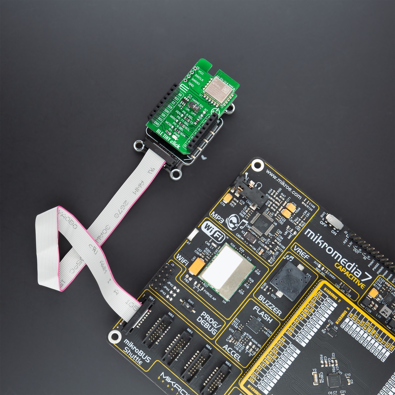
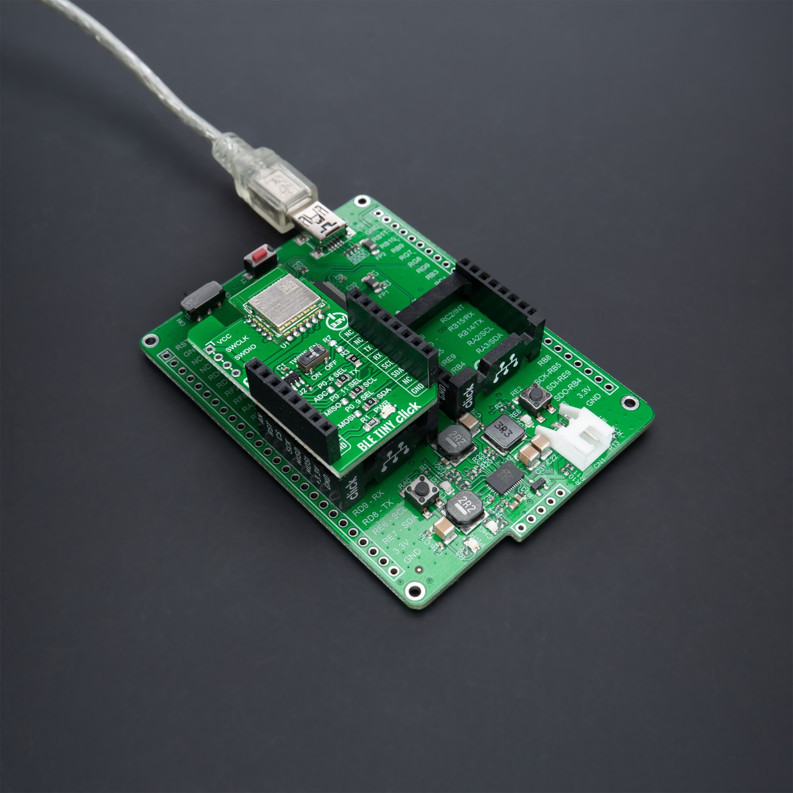
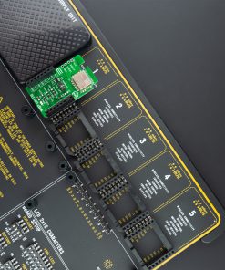
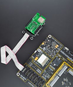
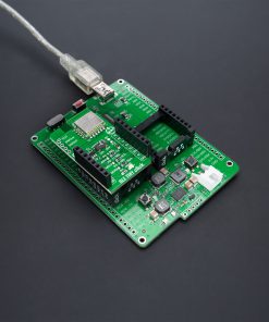
BLE TINY Click is supported by a mikroSDK compliant library, which includes functions that simplify software development. This Click board™ comes as a fully tested product, ready to be used on a system equipped with the mikroBUS™ socket.
Stock: Lead-time applicable.
| 5+ | R299.25 |
| 10+ | R283.50 |
| 15+ | R267.75 |
| 20+ | R257.67 |
How does it work?
BLE TINY Click is based on the DA14531MOD, SmartBond TINY™ module based on the world’s smallest and lowest power Bluetooth 5.1 System-on-Chip (SoC) from Renesas. The DA14531 is based on the powerful 32-bit Arm Cortex-M0+ with integrated memories and analog and digital peripherals. It comes with next-generation Codeless software that allows the design of Bluetooth applications without Bluetooth knowledge or advanced programming skills, using a comprehensive set of AT commands.

This module is supported with software to lower the threshold of using BLE technology. The DA14531 comes with configurable DSPS (serial port service) and next-generation Codeless software to design Bluetooth applications without Bluetooth knowledge or advanced programming skills. It is specifically optimized to significantly reduce the cost of adding Bluetooth low energy functionality to an IoT system. The SmartBond TINY module is certified for worldwide operation, with Federal Communications Commission (FCC) certification for the Americas and CE certification for Europe.
BLE TINY Click communicates with MCU using the Single-Wire UART interface as its default communication protocol for exchanging AT commands with the host and data transfer. A switch labeled as 1WIRE EN is used to activate this communication, which allows the module to establish communication via the Single-Wire UART Receive and Transmit pin, or only via the standard UART TX pin.
For that purpose, this Click board™ uses the 74LVC1G3157 multiplexer to avoid conflict with other functions driven by the same GPIOs. In this way, the user is given the option of using the P0_6 pin, which carries a dual function, a UART TX pin, or a pin to be used for the ADC’s analog pin. The function of this pin is selected by populating the appropriate jumper labeled as P0_6 SEL.
The DA14531 comes in with a predefined default configuration. However, due to the low GPIO pin count, several functions are multiplexed and can be enabled as needed through onboard jumpers. The users can also use other interfaces such as SPI or I2C to configure the module and write the library by themselves by populating the appropriate jumpers (P0_11 and P0_9 SEL).
BLE TINY Click also provides a JTAG interface with SWDIO data and SWCLK clock signals available on header J1. This way, the user has the opportunity to program a particular version of the CodeLess software via the JTAG interface, which is required by the DA14531 module itself. Also, this Click board™ can be reset through the Hardware Reset pin, labeled as RST on the mikroBUS™ socket, by setting this pin to a high logic state.
This Click board™ can be operated only with a 3.3V logic voltage level. The board must perform appropriate logic voltage level conversion before using MCUs with different logic levels. Also, it comes equipped with a library containing functions and an example code that can be used as a reference for further development.
CodeLess Firmware
The integrated next-generation Codeless firmware v2.0 is programmed in the built-in Flash of the DA14531 module and allows you to quickly get started with wireless IoT applications without developing a single line of code. It uses the well-known concept of AT Commands that can be used to perform various tasks; in particular, control of BLE connectivity (connect/disconnect, scan for nearby devices, report BLE address…), interaction with the environment/sensor readout (set GPIOs, read external interfaces, report GPIO status…), and more. For the complete information on available AT commands supported with firmware, please refer to the CodeLess User Manual, which covers all the information related to CodeLess.
Specifications
Type
BT/BLE
Applications
Can be used for wireless networking in portable medical, remote controls, industrial applications, asset tags and beacons, and more.
On-board modules
DA14531MOD – SmartBond TINY™ module based on the world’s smallest and lowest power Bluetooth 5.1 System-on-Chip (SoC) from Renesas
Key Features
Compatible with Bluetooth v5.1, integrated ARM Cortex M0+, memories and peripherals, low power consumption, configurable DSPS and next generation Codeless software, and more.
Interface
Analog,I2C,SPI,UART
Feature
No ClickID
Compatibility
mikroBUS™
Click board size
M (42.9 x 25.4 mm)
Input Voltage
3.3V
Pinout diagram
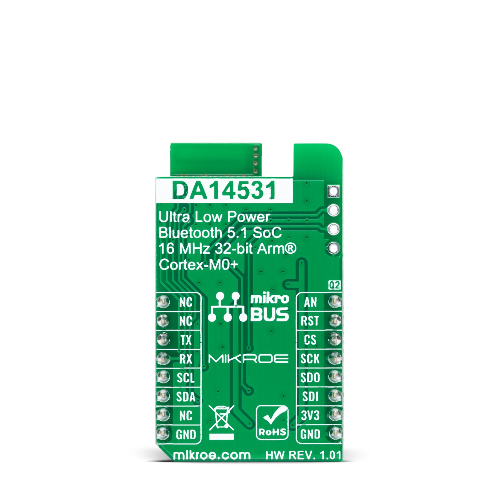
This table shows how the pinout on BLE TINY Click corresponds to the pinout on the mikroBUS™ socket (the latter shown in the two middle columns).
Onboard settings and indicators
| Label | Name | Default | Description |
|---|---|---|---|
| LD1 | PWR | – | Power LED Indicator |
| SW2 | – | Right | ADC_IN/UART_TX Output Selection: Left position ADC_IN, Right position UART_TX |
| SW3-SW4 | – | Right | Communication Interface Selection SPI/I2C: Left position SPI, Right position I2C |
| J1 | – | Unpopulated | JTAG Header for programming DA14531 module |
BLE TINY Click electrical specifications
| Description | Min | Typ | Max | Unit |
|---|---|---|---|---|
| Supply Voltage | – | 3.3 | – | V |
| Frequency Range | 2.4 | – | 2.4835 | GHz |
| Receiver Sensitivity | – | -93 | – | dBm |
| Output Power | – | 2.2 | – | dBm |
Software Support
We provide a library for the BLE TINY Click as well as a demo application (example), developed using MikroElektronika compilers. The demo can run on all the main MikroElektronika development boards.
Package can be downloaded/installed directly from NECTO Studio Package Manager(recommended way), downloaded from our LibStock™ or found on mikroE github account.
Library Description
This library contains API for BLE TINY Click driver.
Key functions:
bletiny_cfg_setup– Config Object Initialization function.bletiny_init– Initialization function.bletiny_default_cfg– Click Default Configuration function.
Examples description
void application_task ( void )
{
    static uint8_t info = 0;
    switch ( example_type )
    {
        case BLETINY_I2C_EXAMPLE:
        {
            if (!info)
            {
                info++;
                log_printf( &logger, " I2C examplern" );
                bletiny_process( );
                bletiny_clear_app_buf( );
            }
            bletiny_i2c_example( );
            break;
        }
        case BLETINY_SPI_EXAMPLE:
        {
            if (!info)
            {
                info++;
                log_printf( &logger, " SPI examplern" );
                bletiny_process( );
                bletiny_clear_app_buf( );
            }
            bletiny_spi_example( );
            break;
        }
        case BLETINY_APP_CTRL:
        {
            if (!info)
            {
                info++;
                log_printf( &logger, " Application examplern" );
                bletiny_process( );
                bletiny_clear_app_buf( );
            }
            bletiny_application_example( );
            break;
        }
        default:
        {
            break;
        }
    }
}
The full application code, and ready to use projects can be installed directly from NECTO Studio Package Manager(recommended way), downloaded from our LibStock™ or found on mikroE github account.
Other mikroE Libraries used in the example:
- MikroSDK.Board
- MikroSDK.Log
- Click.BLETINY
Additional notes and informations
Depending on the development board you are using, you may need USB UART click, USB UART 2 click or RS232 click to connect to your PC, for development systems with no UART to USB interface available on the board. The terminal available in all MikroElektronika compilers, or any other terminal application of your choice, can be used to read the message.
mikroSDK
This Click board™ is supported with mikroSDK – MikroElektronika Software Development Kit. To ensure proper operation of mikroSDK compliant Click board™ demo applications, mikroSDK should be downloaded from the LibStock and installed for the compiler you are using.
For more information about mikroSDK, visit the official page.
Resources
Downloads
| Weight | 19 g |
|---|---|
| Brand | MikroElektronika |


