How does it work?
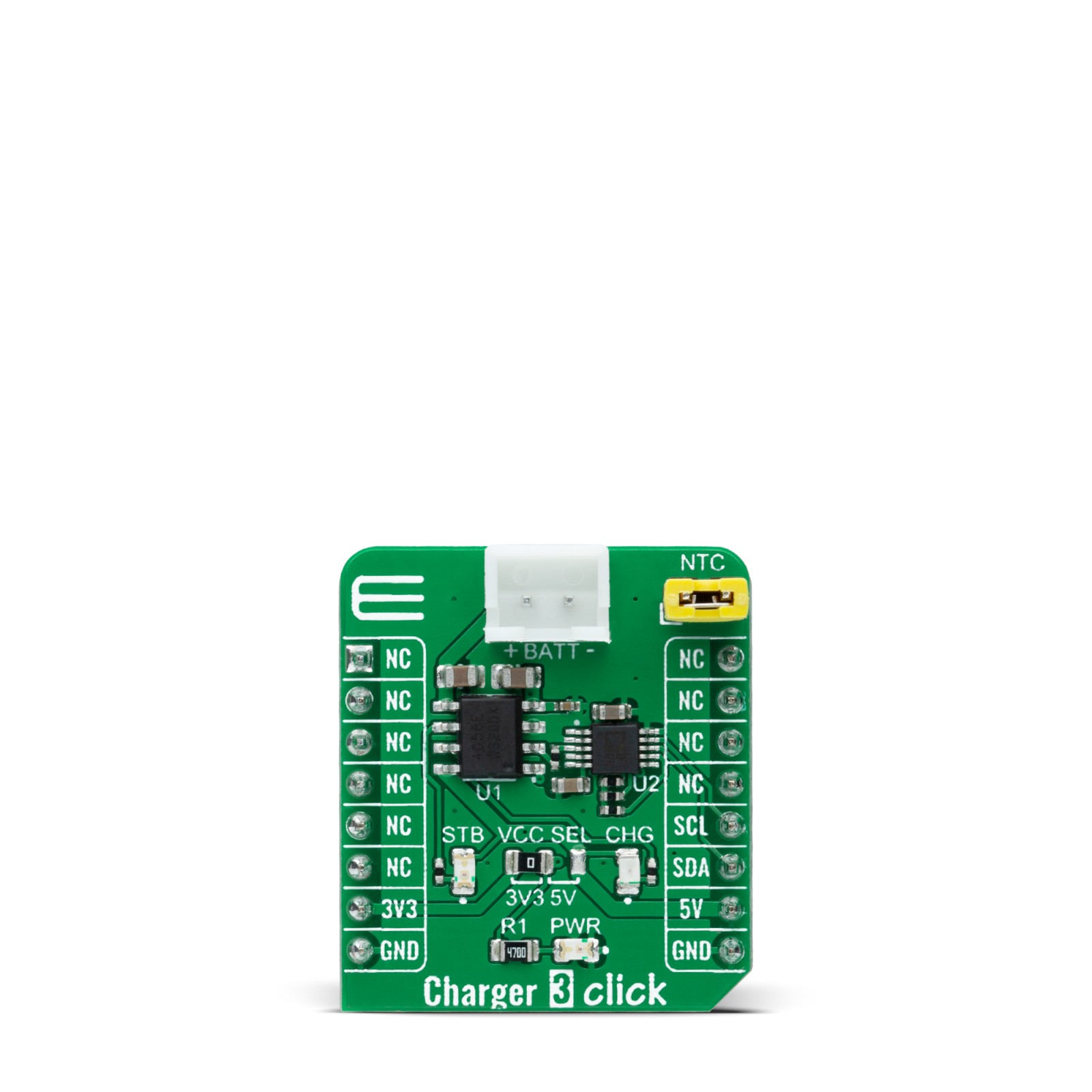
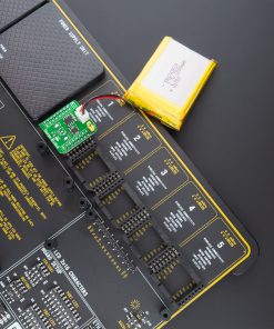
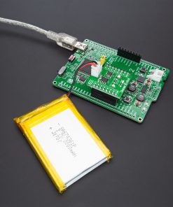
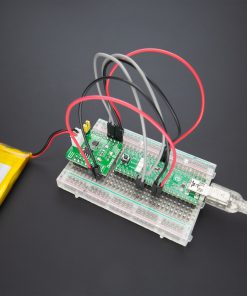
Charger 3 Click is based on the TP4056, a complete constant-current/constant-voltage linear charger for single-cell lithium-ion batteries from NanJing Top Power ASIC Corp. This standalone battery charger automatically terminates the charge cycle when the charge current drops to 1/10th of the programmed value after reaching the final float voltage. Thermal feedback regulates the charging current to limit the die temperature during high power operation or high ambient temperature. It also features current monitoring, under-voltage lockout, automatic recharge, and two LEDs to indicate charge termination and the presence of an input voltage.
The charge voltage of the TP4056 is specified at 4.2V with 1.5% accuracy, with the charge current pin programmable up to 1000mA via an onboard single-channel digital potentiometer, the AD5175 from Analog Devices, controllable through the I2C compatible digital interface. When the TP4056 is in a pre-charge mode, this pins voltage is regulated to 0.2V, while in constant-charge current mode voltage is regulated to 2V. During the charging process, the voltage on this pin can be used to measure the charge current.
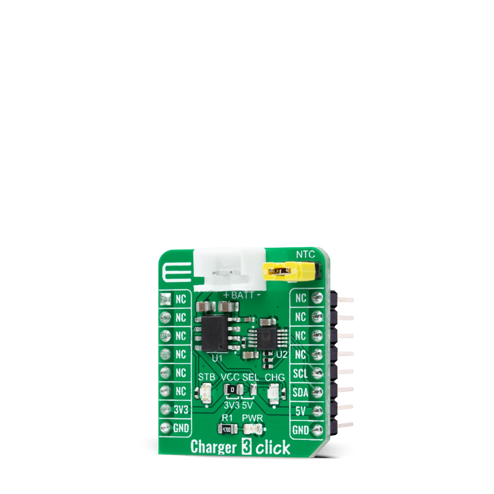
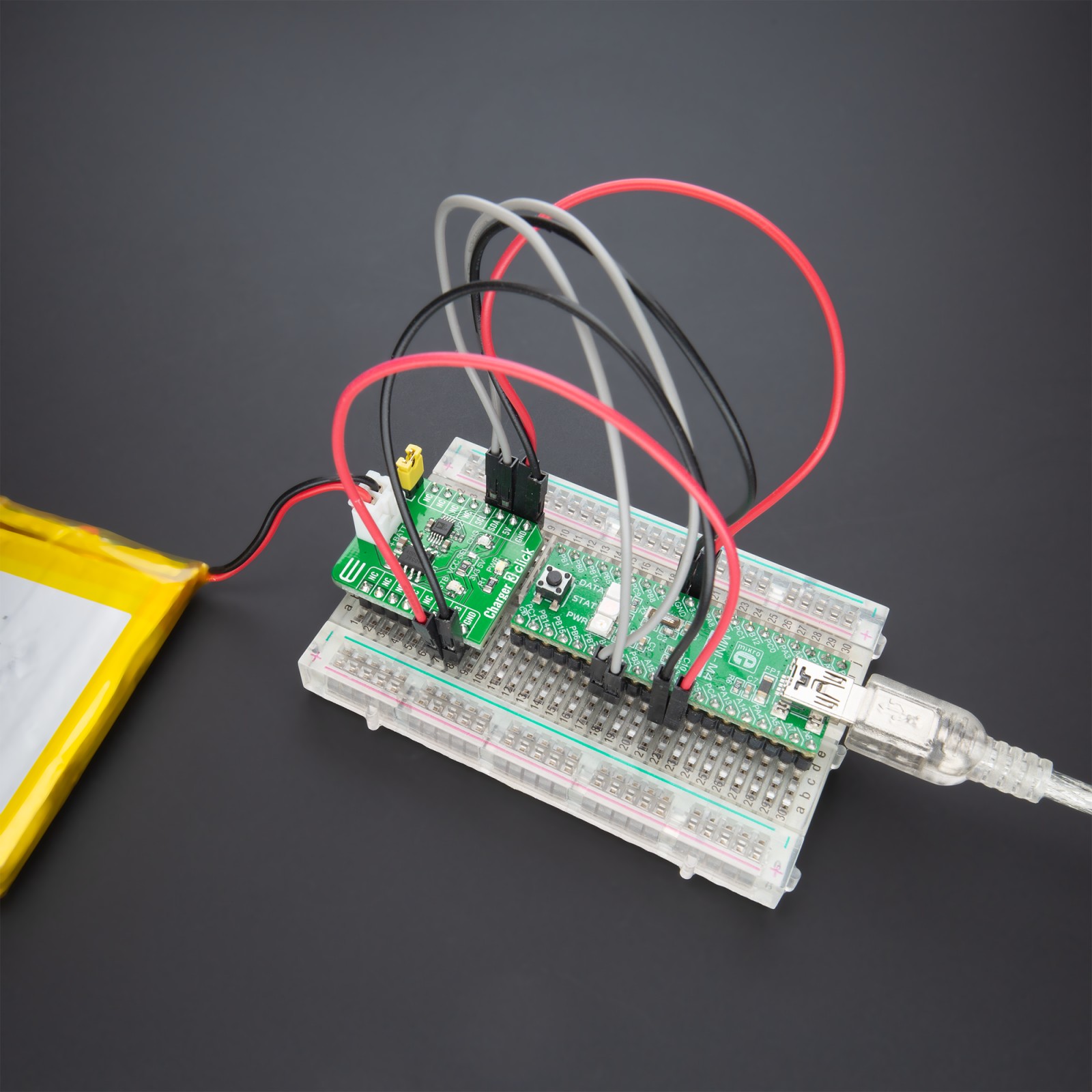
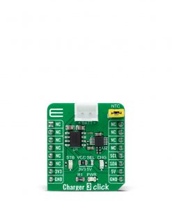
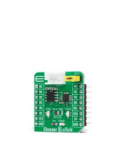
Charger 3 Click has the possibility of connecting an external temperature sensor on the onboard header labeled as NTC. If the voltage of this pin is below 45% or above 80% of supply voltage for more than 0.15s, this means that the battery’s temperature is too high or too low, suspending the charging process. Alongside this feature, this Click board™ also has two LEDs to indicate charge termination and the presence of an input voltage, red LED labeled as CHG indicating charging process, and green LED labeled as STB for ‘charged’ status.
This Click board™ is designed to operate with both 3.3V and 5V logic voltage levels selected via the VCC SEL jumper. It allows for both 3.3V and 5V capable MCUs to use the I2C communication lines properly. However, the Click board™ comes equipped with a library that contains functions and an example code that can be used, as a reference, for further development.
Specifications
Type
Battery charger
Applications
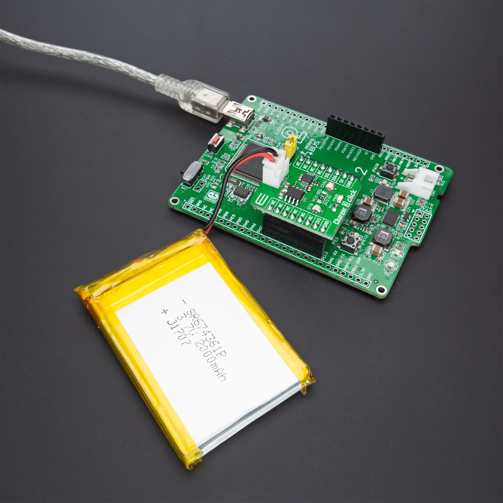
Can be used for the development of multiple Li-ion battery cell charging applications
On-board modules
TP4056 – complete constant-current/constant-voltage linear charger for single-cell lithium-ion batteries from NanJing Top Power ASIC Corp
AD5175 – single-channel digital potentiometer from Analog Devices
Key Features
Programmable charge current up to 1000mA, complete linear charger for single-cell Lithium-Ion batteries, constant-current/constant-voltage, two charge status indicators, and more
Interface
I2C
Feature
No ClickID
Compatibility
mikroBUS™
Click board size
S (28.6 x 25.4 mm)
Input Voltage
3.3V or 5V
Pinout diagram
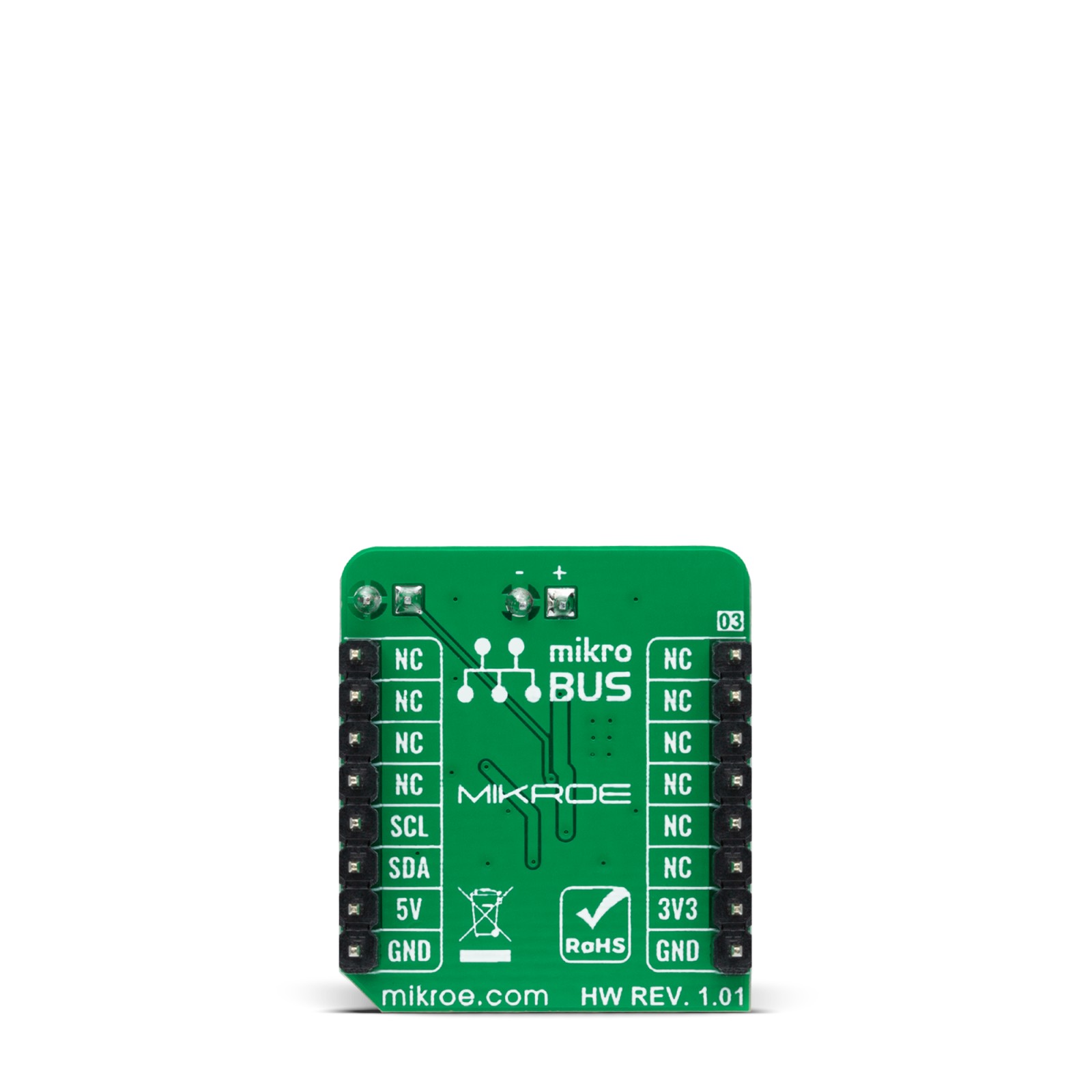
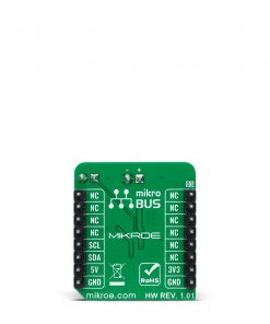
This table shows how the pinout on Charger 3 Click corresponds to the pinout on the mikroBUS™ socket (the latter shown in the two middle columns).
Onboard settings and indicators
Label | Name | Default | Description |
---|---|---|---|
LD1 | PWR | – | Power LED Indicator |
LD2 | CHG | – | Charging State LED Indicator |
LD3 | STB | – | Standby State LED Indicator |
JP1 | VCC SEL | Left | Logic Level Voltage Selection 3V3/5V: Left position 3V3, Right position 5V |
J1 | NTC | Populated | External Temperature Sensor Header |
Charger 3 Click electrical specifications
Description | Min | Typ | Max | Unit |
---|---|---|---|---|
Supply Voltage | 3.3 | – | 5 | V |
Battery Charge Current Range | 130 | – | 1000 | mA |
Operating Temperature Range | -40 | +25 | +85 | °C |
Software Support
We provide a library for the Charger 3 Click as well as a demo application (example), developed using MikroElektronika compilers. The demo can run on all the main MikroElektronika development boards.
Package can be downloaded/installed directly from NECTO Studio Package Manager(recommended way), downloaded from our LibStock™ or found on mikroE github account.
Library Description
This library contains API for Charger 3 Click driver.
Key functions:
void charger3_cfg_setup ( charger3_cfg_t *cfg );
– Config Object Initialization function.CHARGER3_RETVAL charger3_init ( charger3_t *ctx, charger3_cfg_t *cfg );
– Initialization function.void charger3_default_cfg ( charger3_t *ctx );
– Click Default Configuration function.
Examples description
This example demonstrates the utilization of Charger 3 Click.
The demo application is composed of two sections :
void application_task ( void ) { float result; charger3_set_current( &charger3, 0.4 ); Delay_ms( 1000 ); result = charger3_calc_digipot_res( &charger3 ); log_printf( &logger, " Digipot res value: %.2f ohmrn", result ); log_printf( &logger, " ------------------------------------rn" ); Delay_ms( 5000 ); }
While the resistance of the AD5175 can be directly set and read, the total resistance value on the PROG pin should be accounted for ( this means an additional 1kohm in series ) setting of the battery charging current.
The full application code, and ready to use projects can be installed directly from NECTO Studio Package Manager(recommended way), downloaded from our LibStock™ or found on mikroE github account.
Other mikroE Libraries used in the example:
- MikroSDK.Board
- MikroSDK.Log
- Click.Charger3
Additional notes and informations
Depending on the development board you are using, you may need USB UART click, USB UART 2 click or RS232 click to connect to your PC, for development systems with no UART to USB interface available on the board. The terminal available in all MikroElektronika compilers, or any other terminal application of your choice, can be used to read the message.
mikroSDK
This Click board™ is supported with mikroSDK – MikroElektronika Software Development Kit. To ensure proper operation of mikroSDK compliant Click board™ demo applications, mikroSDK should be downloaded from the LibStock and installed for the compiler you are using.
For more information about mikroSDK, visit the official page.