LSM303AGR Click
R435.00 ex. VAT
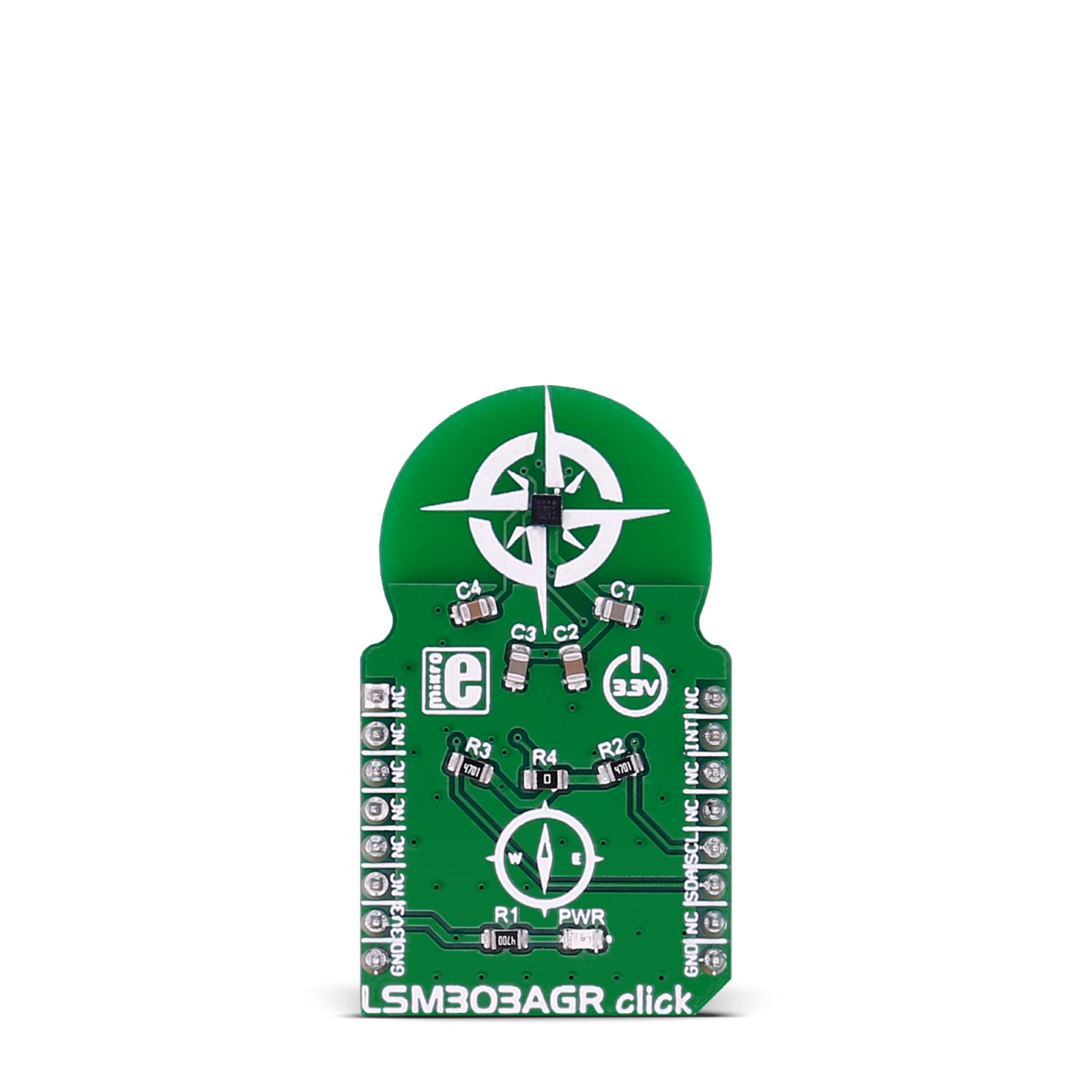
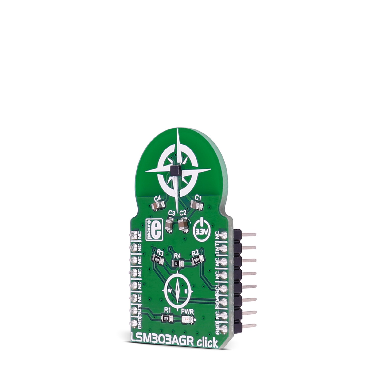
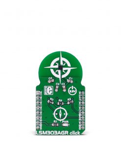
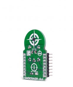
LSM303AGR click is a magnetometer and accelerometer device, capable of sensing both the magnetic and gravitational field along three orthogonal axes. It uses the LSM303AGR from STMicroelectronics, an integrated MEMS IC with plenty of features that allow accurate and reliable sensing, even in presence of foreign objects made of iron and similar materials that exhibit ferromagnetic behavior. An extensive interrupt engine can be programmed to generate an interrupt signal for free-falling events, motion detection, and magnetic field detection. The Click board™ can sense the magnetic field in the range of ±50 G (gauss) and ±2g, ±4g, ±8g, and ±16g selectable ranges for the full-scale acceleration detection (gravity force).
NOTE: Due to the current component shortage on the electronic market lead time and pricing for this product can vary
Stock: Lead-time applicable.
| 5+ | R413.25 |
| 10+ | R391.50 |
| 15+ | R369.75 |
| 20+ | R355.83 |
Additional embedded self-test circuitry allows reliable operation, while the integrated thermometer offers calibration data with no additional circuitry or sensors used. This makes the LSM303AGR sensor a perfect choice for the magnetometer and accelerometer Click board™, which can be used for development of a wide range of applications, including electronic compasses, position detectors, motion or tap activated features, gaming equipment, intelligent handheld devices power saving, free-fall detection, and similar.
How does it work?
The LSM303AGR is a low power and high-performance sensor IC featuring a digital linear acceleration sensor, and a digital magnetic sensor, capable of sensing magnetic and gravitational fields in all three axes. The sensor is a highly integrated system in package (SIP), offering two independent sensors, charge amplifiers, A/D converters, and control logic sections. There are two independent I2C slave addresses for each of the sensors: 0011001b is the slave address of the accelerometer, while the 0011110b is the slave address of the magnetic sensor. These are 7bit addresses, to complete the address sequence, an R/W bit needs to be added at the end.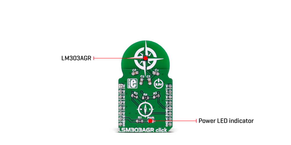
An interrupt pin (INT_MAG/DRDY) allows the interrupt generated by an event within the LSM303AGR IC, to alert the host MCU. This pin is routed to the mikroBUS™ INT pin. The power of the LSM303AGR IC lies in its configurable interrupt engine. The function, threshold, and timing of the interrupt signal on the INT pin can be completely defined by the user. Its behavior can be programmed by setting a range of appropriate registers via the I2C bus. The sensor offers detection of many events, caused either by the sensors themselves or by the error/status events within the sensor IC. For example, the interrupt can be generated if there is data ready to be transferred to the host MCU if the FIFO buffer overflow occurred and so on. A combination of events is also available, with either ‘OR’ or ‘AND’ function between the generated events. It allows developing HID applications, which react on tapping, moving, positioning, etc.
The LSM303AGR device offers digital filtering, compensation, self-test, and more. It allows resolution, sampling time and power consumption to be adjusted, allowing the Click board™ to be tailored to any application. Trimming values for zero-g level, zero-gauss level, and sensitivity adjustment are stored into the internal non-volatile memory and are copied to the registers upon restart. This allows the sensor to perform accurate measurements without repeated calibration after each power-up cycle.
Another feature used to increase the accuracy of the sensor is the hard-iron compensation, which compensates the readings, in cases when an object with magnetic properties is placed near the sensor, permanently biasing the output values. Six registers hold magnetic values for the compensation and are automatically subtracted from readings. Many signal processing features such as the low-pass and high-pass filtering, also help to obtain accurate and reliable readings from this sensor.
A self-test procedure can be used to verify the functionality of the device. The internal current generates an internal magnetic field, which is then sensed by the sensors. The readings during self-test should look like in the table, given in the LSM303AGR datasheet. If these readings look differently, a particular device can be discarded.
The device contains a FIFO buffer, which can be used for the accelerometer sensor only. It is 32 levels deep, allowing 32 sets of readings along X, Y, and Z axes to be stored. The buffer can be bypassed, it can be fixed so that new data is discarded when it is full, and it can be set to streaming mode so that the new data pushes out the oldest information from the buffer. An interrupt can be triggered if a programmed threshold is exceeded so that the buffer can be read before the data is lost.
The sampling frequency and the resolution can be selected from 1Hz up to 5.736 kHz and from 8 bits up to 12 bits. These settings affect the power consumption. The device can work in normal mode, high-resolution mode, and low power mode. This affects the acquisition time as well as the power consumption. In addition, the device can work in continuous mode, or in a single shot mode. A single shot mode allows the device to consume less power, as the single measurement is done on a command, after which device reverts to idle mode and the DRDY (data ready) bit is set. Again, the datasheet of the LSM303AGR offers an in-depth explanation of all the registers and their functionality.
Specifications
Type
Acceleration,Magnetic
Applications
It can be used for developing various applications, including electronic compasses, position detectors, motion or tap activated features, gaming equipment, intelligent handheld devices power saving, free-fall detection, and similar.
On-board modules
LSM303AGR, a compact 3D accelerometer and 3D magnetometer from STMicroelectronics
Key Features
Two independent sensors providing three magnetic field channels and three acceleration channels. Onboard EEPROM with the factory programmed compensation values, permanent magnetic field cancelation, and more
Interface
I2C
Feature
No ClickID
Compatibility
mikroBUS™
Click board size
M (42.9 x 25.4 mm)
Input Voltage
3.3V
Pinout diagram
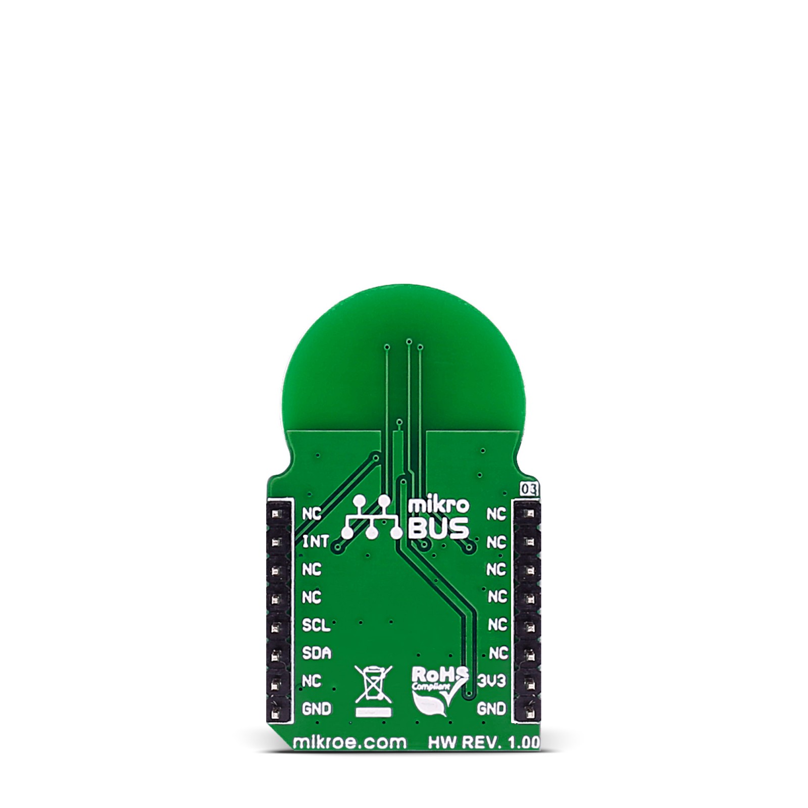
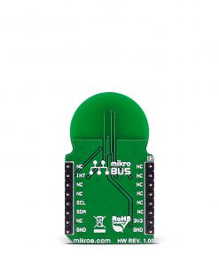
This table shows how the pinout on LSM303AGR click corresponds to the pinout on the mikroBUS™ socket (the latter shown in the two middle columns).
Software Support
We provide a library for the LSM303AGR Click as well as a demo application (example), developed using MIKROE compilers. The demo can run on all the main MIKROE development boards.
Package can be downloaded/installed directly from NECTO Studio Package Manager (recommended), downloaded from our LibStock™ or found on MIKROE github account.
Library Description
This library contains API for LSM303AGR Click driver.
Key functions
-
Reading the raw X axis data and calculating the value
-
Reading the raw X axis data and calculating the value
-
Reading the raw Y axis data and calculating the value
Example Description
This demo example returns magnetic and acceleration values from the LSM303AGR sensor.
 void application_task ( void )
 {
     //  Task implementation.

     log_printf(&logger, "======== Accelerometer data ========rn");

     read_data = lsm303agr_get_acc_axis_x ( &lsm303agr );
     log_printf(&logger, "X Axis : %frn", read_data);

     read_data = lsm303agr_get_acc_axis_y ( &lsm303agr );
     log_printf(&logger, "Y Axis : %frn", read_data);

     read_data = lsm303agr_get_acc_axis_z ( &lsm303agr );
     log_printf(&logger, "Z Axis : %frn", read_data);

     log_printf(&logger, "======== Mangetometer data ========rn");

     read_data = lsm303agr_get_mag_axis_x ( &lsm303agr );
     log_printf(&logger, "X Axis : %frn", read_data);

     read_data = lsm303agr_get_mag_axis_y ( &lsm303agr );
     log_printf(&logger, "Y Axis : %frn", read_data);

     read_data = lsm303agr_get_mag_axis_z ( &lsm303agr );
     log_printf(&logger, "Z Axis : %frn", read_data);

     Delay_ms ( 1000 );
 }
The full application code, and ready to use projects can be installed directly from NECTO Studio Package Manager (recommended), downloaded from our LibStock™ or found on MIKROE github account.
Other MIKROE Libraries used in the example:
- MikroSDK.Board
- MikroSDK.Log
- Click.LSM303AGR
Additional notes and informations
Depending on the development board you are using, you may need USB UART click, USB UART 2 Click or RS232 Click to connect to your PC, for development systems with no UART to USB interface available on the board. UART terminal is available in all MIKROE compilers.
mikroSDK
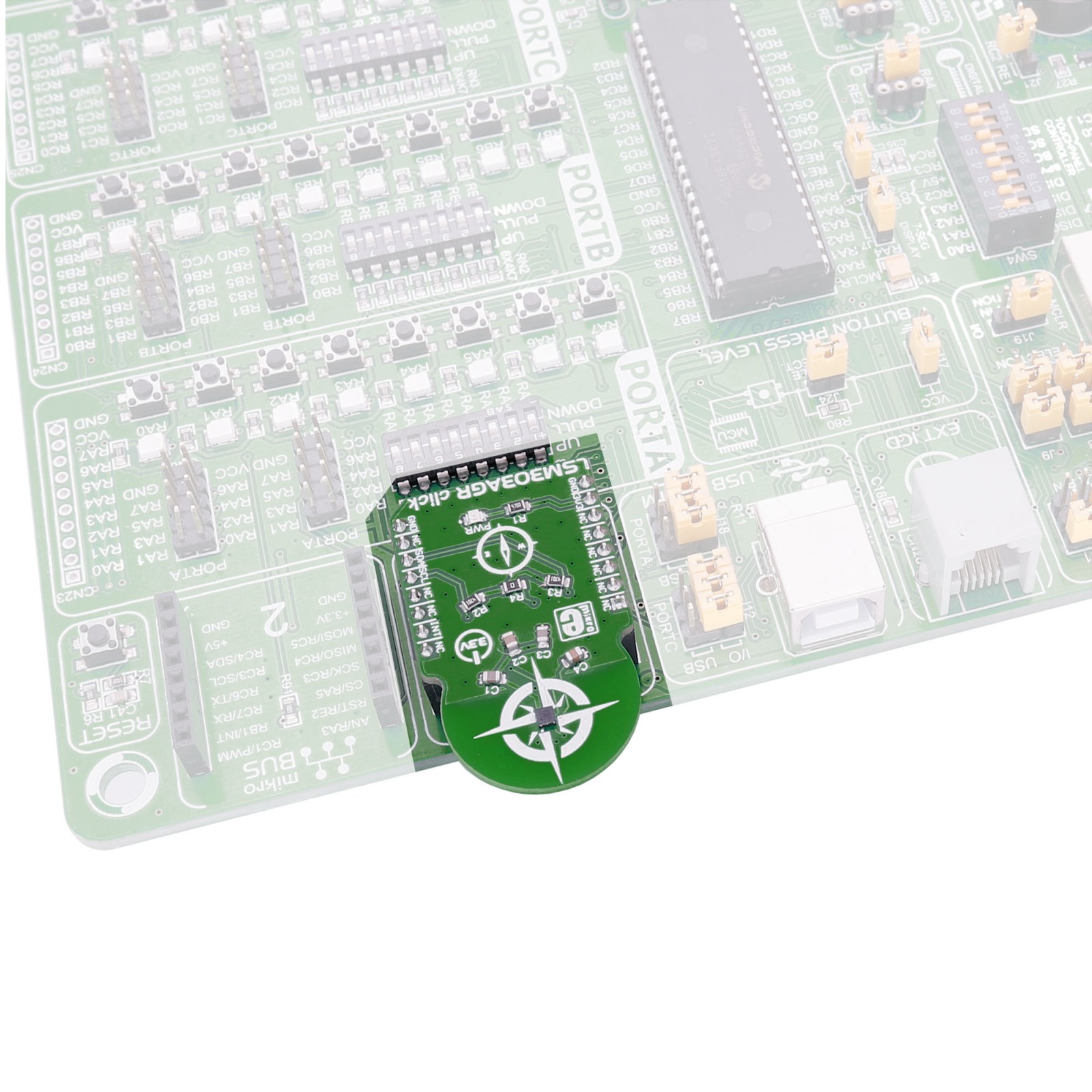
This Click board™ is supported with mikroSDK – MIKROE Software Development Kit. To ensure proper operation of mikroSDK compliant Click board™ demo applications, mikroSDK should be downloaded from the LibStock and installed for the compiler you are using.
For more information about mikroSDK, visit the official page.
Resources
Downloads
| Weight | 18 g |
|---|---|
| Brand | MikroElektronika |

