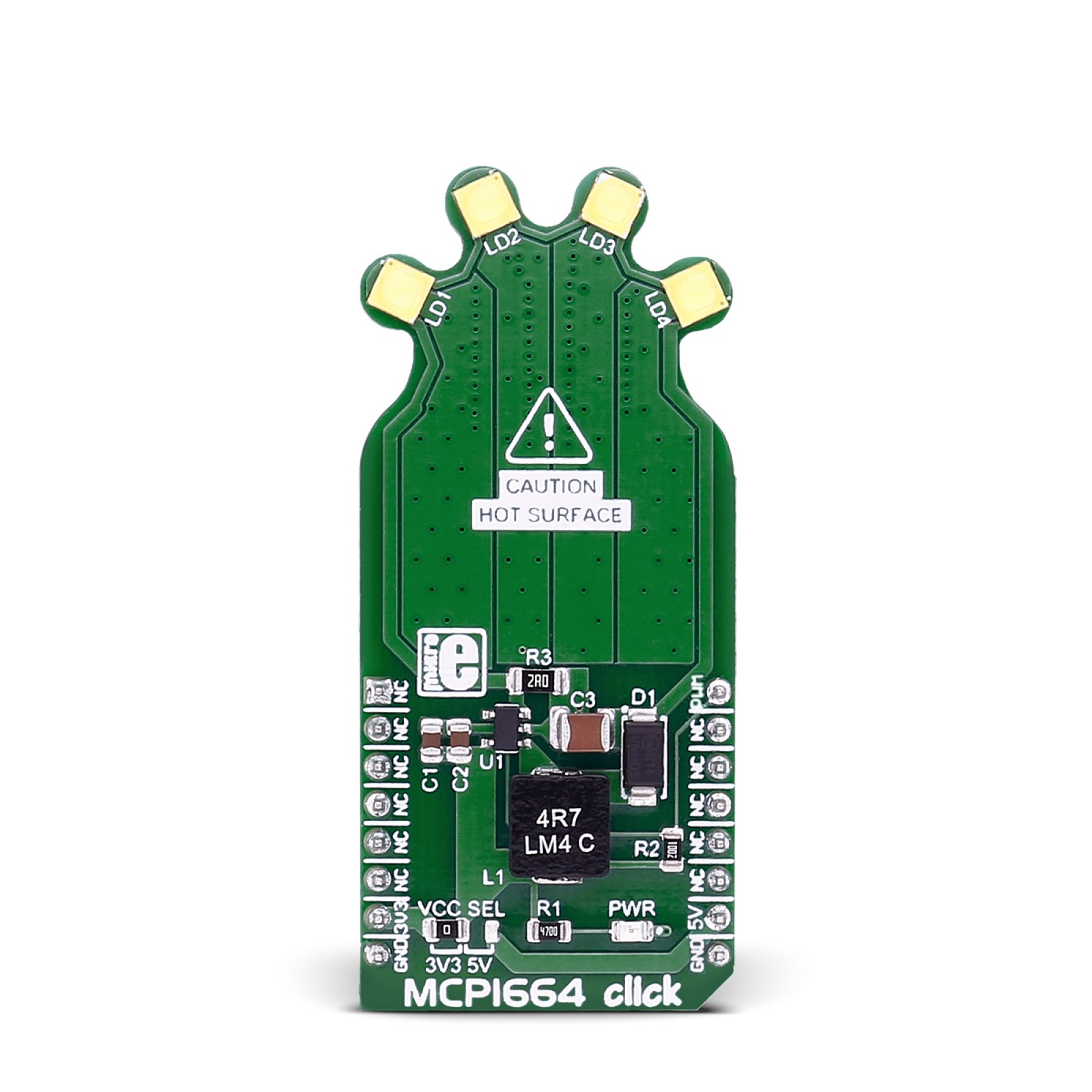
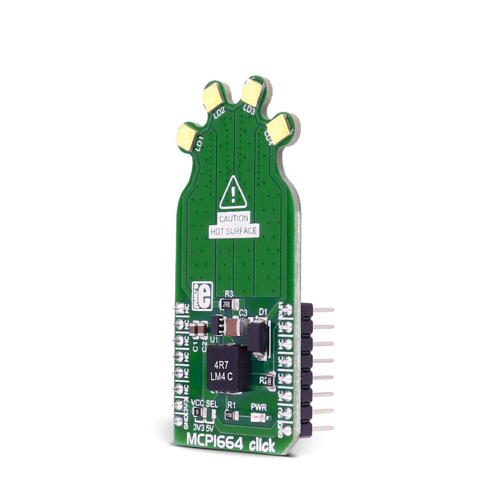
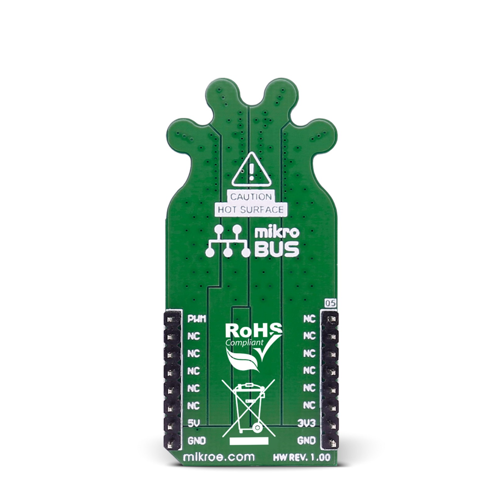
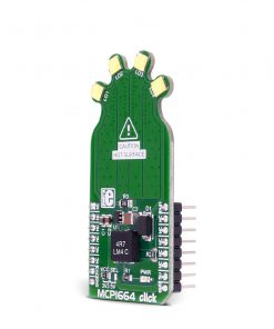
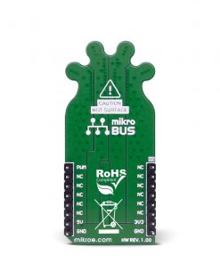
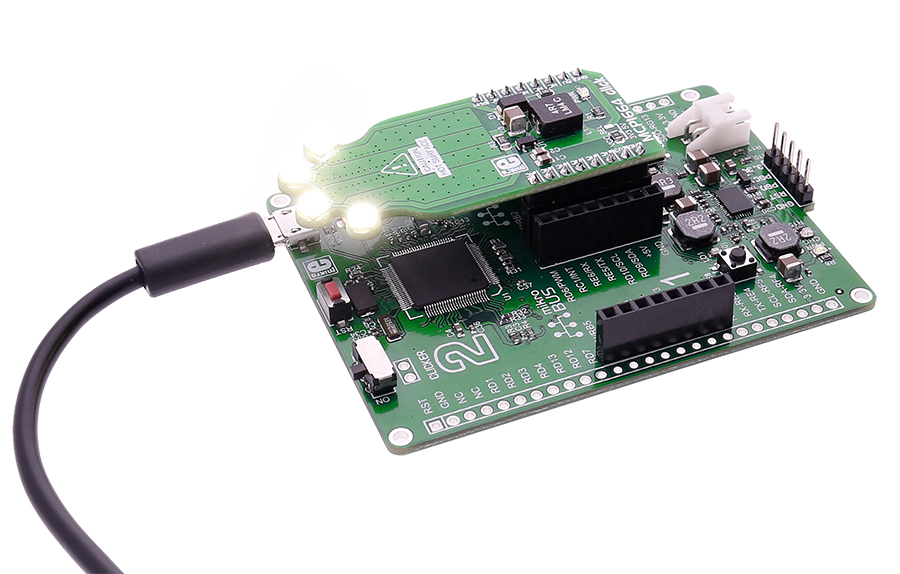
MCP1664 click contains 4 high-power white LEDs. It carries the MCP1664, a high-voltage step-up LED driver from Microchip. MCP1664 click is designed to run on either 3.3V or 5V power supply. It communicates with the target board microcontroller over the PWM pin on the mikroBUS™ line.
How the MCP1664 click works
The click has a power input and a PWM input, so you can set the light intensity at the level you want.
MCP1664 IC features
The MCP1664 is a compact, space-efficient, fixed-frequency, non-synchronous step-up converter optimized to drive multiple strings of LEDs with constant current powered from two and three-cell alkaline or NiMH/NiCd as well as from one-cell Li-Ion or Li-Polymer batteries.
The MCP1664 features an open load protection (OLP) which turns off the operation in situations when the LED string is accidentally disconnected or the feedback pin is short-circuited to GND.
While in Shutdown mode (EN = GND), the device stops switching and consumes 40 nA typical of input current.
Specifications
Type
LED Drivers
Applications
White LED Driver for Backlighting Products, Li-IonBattery LED Lightning Application, etc.
On-board modules
MCP1664 module from Microchip
Key Features
You can set the light intensity
Interface
PWM
Feature
No ClickID
Compatibility
mikroBUS™
Click board size
L (57.15 x 25.4 mm)
Input Voltage
3.3V or 5V
Pinout diagram
This table shows how the pinout on RN4871 click corresponds to the pinout on the mikroBUS™ socket (the latter shown in the two middle columns).
Maximum ratings
Description | Min | Typ | Max | Unit |
---|---|---|---|---|
Supply Voltage | 2.4 | 5.5 | V | |
Max Out Voltage | 32 | V | ||
Max Out Current 4.2V Vin 8 LEDs | 150 | mA | ||
Max Out Current 3.3V Vin 4 LEDs | 200 | mA | ||
Max Out Current 5.0V Vin 4 LEDs | 300 | mA |
Programming
Code examples for MCP1664 click, written for MikroElektronika hardware and compilers are available on Libstock.
Code snippet
This code snippet shows basic control of light brightness with PWM. The duty cycle is controled with the potentiometer P1.
01 uint16_t current_duty; 02 uint16_t adc_rd; 03 void MCU_Init() 04 { 05 TRISC = 0; // designate PORTC pins as output 06 LATC = 0; // set PORTC to 0 07 PWM2_Init( 5000 ); // Initialize PWM2 module at 5KHz 08 } 09 void main() 10 { 11 MCU_Init(); 12 current_duty = 0; 13 PWM2_Start(); 14 PWM2_Set_Duty(current_duty); 15 while ( 1 ) // Playing with Potentiometer P1 you can control current PWM duty cycle 16 { 17 adc_rd = ADC_Read(1) & 0x0000FFFF; // Read 10 - bit ADC value and set newly acquired 8 - bit PWM duty 18 current_duty = adc_rd / 4 ; 19 PWM2_Set_Duty(current_duty ); // Set newly acquired duty 20 } 21 22 }