How does it work?
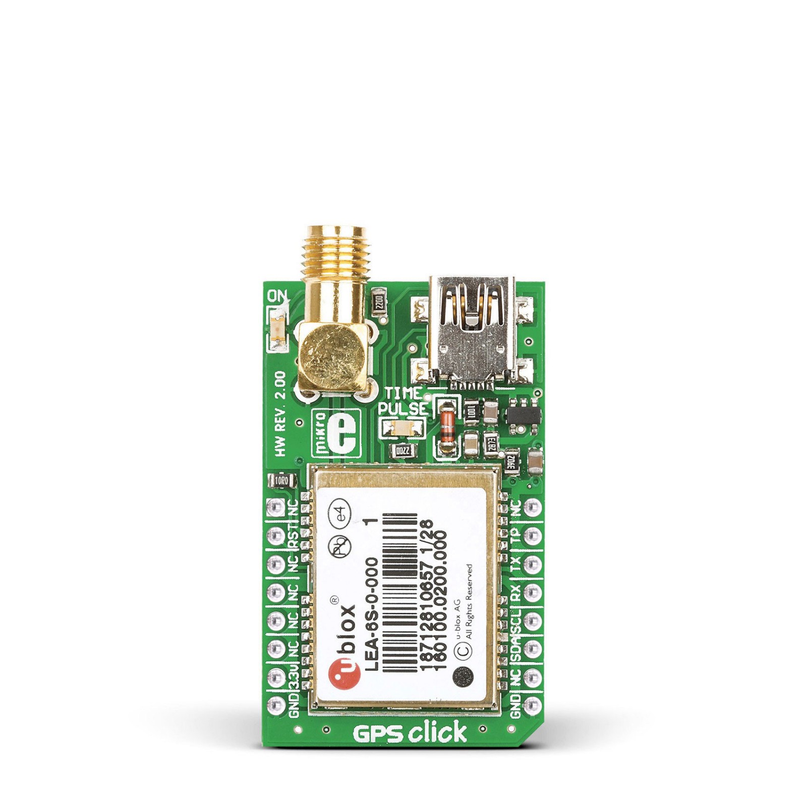
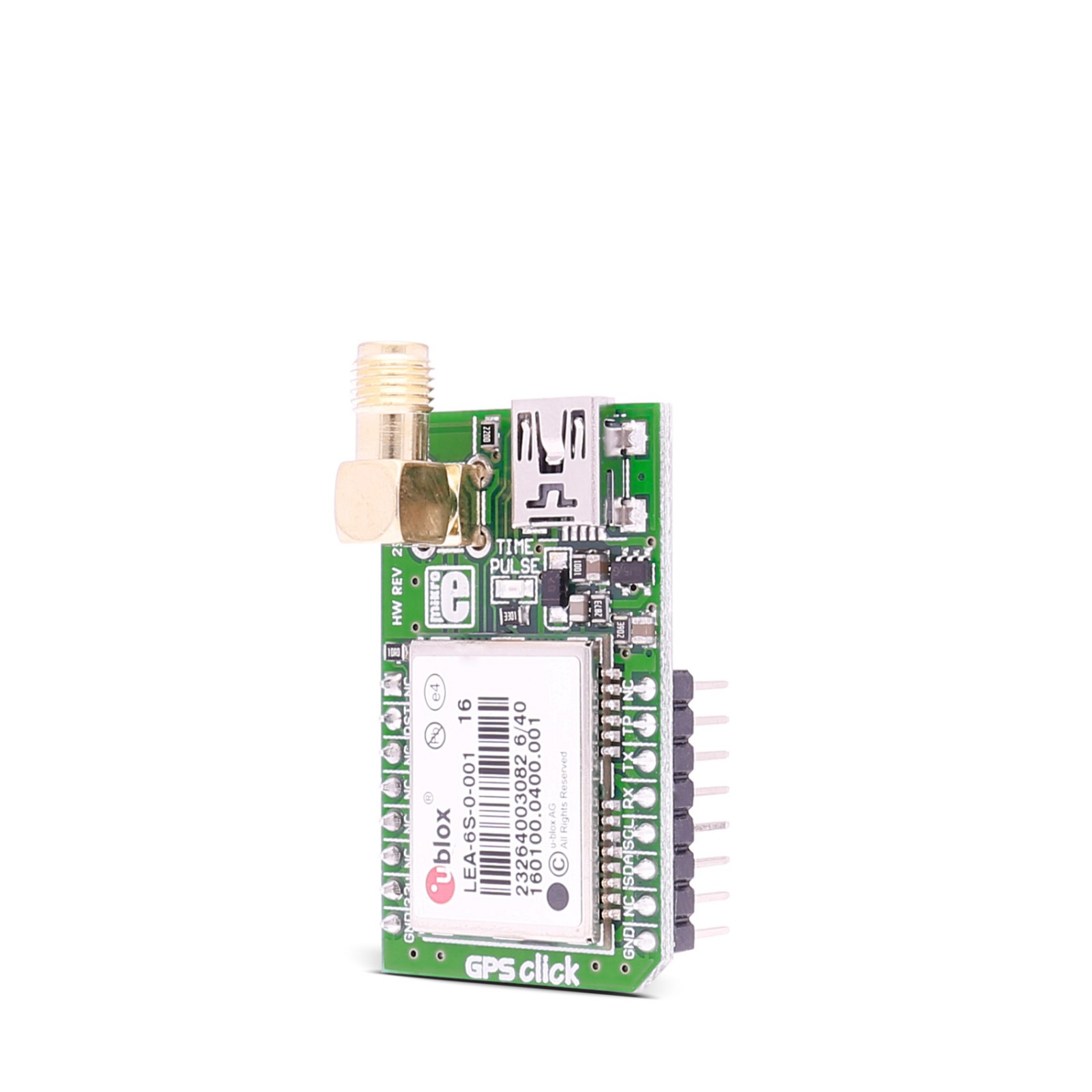
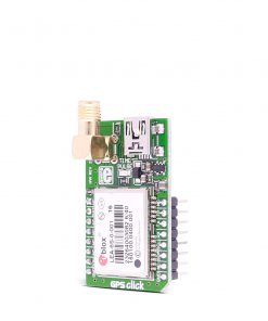
GPS Click is based on the LEA-6S, a high-performance position engine module from u-blox. The versatile, standalone LEA-6S receiver combines extensive features with flexible connectivity options. Its ease of integration results in fast time-to-market for various automotive and industrial applications. The positioning engine consists of cold start navigation, AssitsNow Autonomous for faster acquisition, configurable power management, a hybrid GPS/SBAS engine (WAAS, EGNOS, MSAS), and anti-jamming technology. The GPS module needs an SMA GPS antenna for the GPS applications, which can be bought from MIKROE separately.
Different power modes (Maximum performance, Eco, Power Save) allow you to control the acquisition and tracking engines to balance performance and power consumption. During a Cold start, a receiver in Maximum Performance Mode continuously deploys the acquisition engine to search for all satellites. Once the receiver has a position fix (or if pre-positioning information is available), the acquisition engine continues to search for all visible satellites that are not being tracked. During a Cold start, a receiver in Eco Mode works exactly as in Maximum Performance Mode. Once a position can be calculated and a sufficient number of satellites are tracked, the acquisition engine is powered off, resulting in significant power savings. The tracking engine continuously tracks acquired satellites and acquires other available or emerging satellites. Note that even if the acquisition engine is powered off, satellites continue to be acquired. Power Save Mode reduces system power consumption by selectively switching receiver parts on and off.
GPS click can simultaneously track up to 16 satellites while searching for new ones. The LEA-6S module’s TTFF (time to first fix) is less than one second — this is the measure of time necessary for a GPS receiver to get satellite signals and navigation data, and based on this information, calculate a position (a fix). The GPS Click is equipped with a TIME PULSE LED as a 1PPS LED for that purpose. The Time Pulse has a 99% accuracy, and its frequency range is adjustable from 0.25Hz to 1kHz. The Time Pulse can be tracked over the TP pin of the mikroBUS™ socket, too.
GPS Click as default communication with the host MCU uses a standard 2-Wire UART interface with commonly used UART RX and TX and supports 4800 and 9600bps, depending on settings. The I2C-compatible Display Data Channel (DDC) can also be used to interface host MCU. It is a standard mode compliant with a maximum bandwidth of 100kbps. On the other hand, GPS Click supports a full-speed USB 2.0 at 1.2Mbps. If such a case emerges, you can always reset the module over the RST pin.
This Click board™ can be operated only with a 3.3V logic voltage level. The board must perform appropriate logic voltage level conversion before using MCUs with different logic levels. Also, this Click board™ comes equipped with a library containing easy-to-use functions and an example code that can be used as a reference for further development.
Specifications
Type
GPS/GNSS
Applications
Can be used for the development of a broad spectrum of GPS applications where performance, cost, and time to market are prime considerations
On-board modules
LEA-6S – high-performance position engine module from u-blox
Key Features
SuperSense Indoor GPS, faster acquisition with AssistNow Autonomous, hybrid GPS/SBAS engine (WAAS, EGNOS, MSAS), anti-jamming technology, configurable power management, flexible connectivity options, standalone device, USB usage, and more
Interface
I2C,UART,USB
Feature
No ClickID
Compatibility
mikroBUS™
Click board size
M (42.9 x 25.4 mm)
Input Voltage
3.3V
Pinout diagram
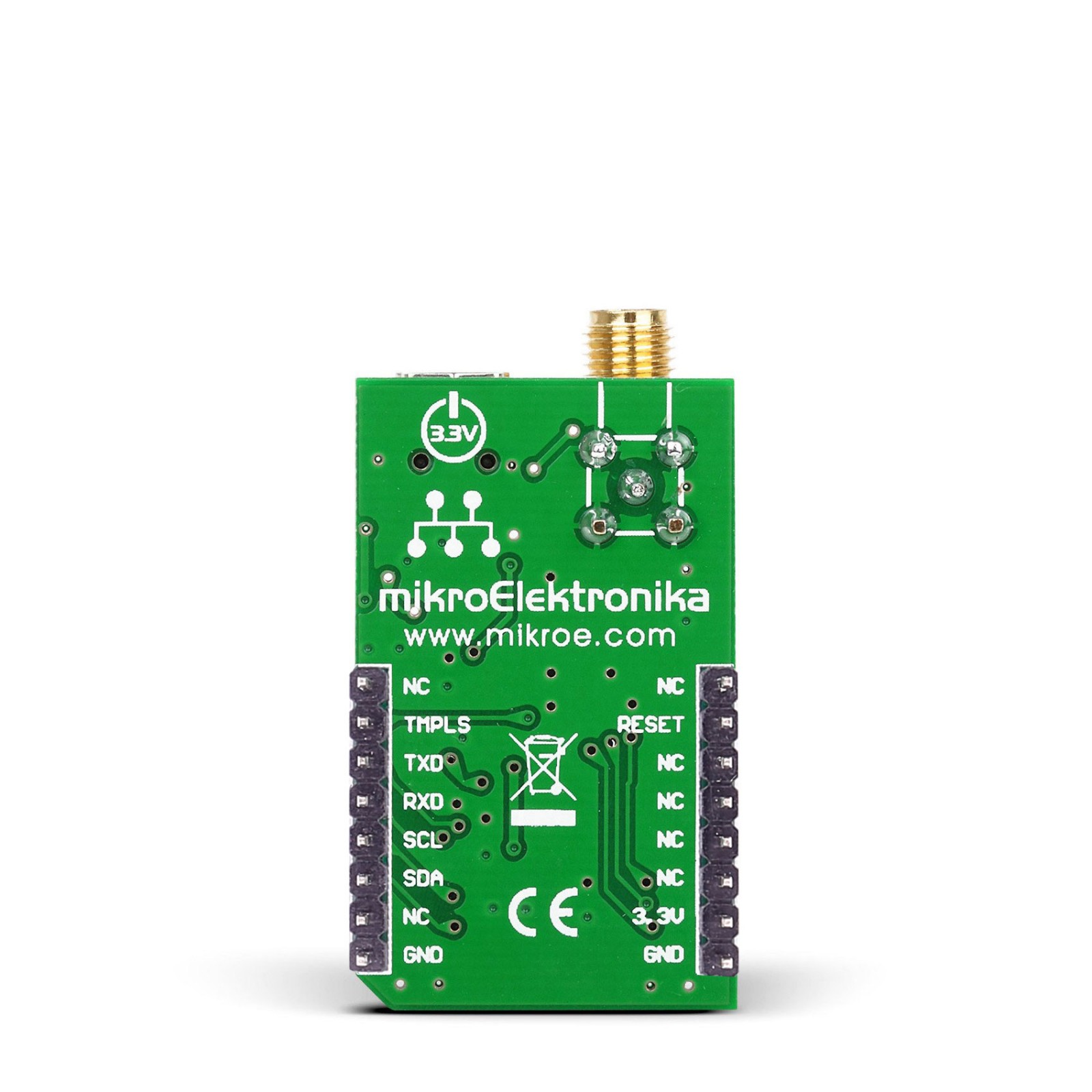
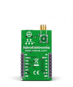
This table shows how the pinout on GPS Click corresponds to the pinout on the mikroBUS™ socket (the latter shown in the two middle columns).
Onboard settings and indicators
Label | Name | Default | Description |
---|---|---|---|
– | ON | – | Power LED Indicator |
– | TIME PULSE | – | Time Pulse (1PPS) LED Indicator |
GPS Click electrical specifications
Description | Min | Typ | Max | Unit |
---|---|---|---|---|
Supply Voltage | – | 3.3 | – | V |
Tracking Sensitivity | – | -162 | – | dBm |
Acquisition (Cold Start) | – | – | 26 | s |
Acquisition (Hot Start) | – | – | 1 | s |
Position Accuracy | – | – | <2.5 | CEP |
Software Support
We provide a library for the GPS Click as well as a demo application (example), developed using MIRKOE compilers. The demo can run on all the main MIKROE development boards.
Package can be downloaded/installed directly from NECTO Studio Package Manager(recommended way), downloaded from our LibStock™ or found on Mikroe github account.
Library Description
This library contains API for GPS Click driver.
Key functions
-
Generic parser function.
-
Generic read function.
-
Wake-up module.
Example Description
This example reads and processes data from GPS clicks.
void application_task ( void )
{
gps_process( );
parser_application( current_parser_buf );
}
The full application code, and ready to use projects can be installed directly from NECTO Studio Package Manager(recommended way), downloaded from our LibStock™ or found on Mikroe github account.
Other Mikroe Libraries used in the example:
- MikroSDK.Board
- MikroSDK.Log
- Click.Gps
Additional notes and informations
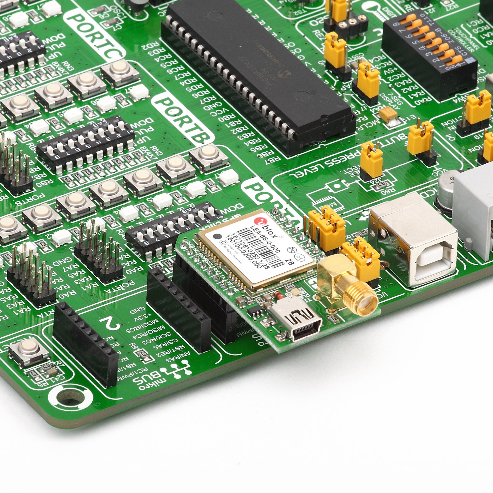
Depending on the development board you are using, you may need USB UART click, USB UART 2 Click or RS232 Click to connect to your PC, for development systems with no UART to USB interface available on the board. UART terminal is available in all MIKROE compilers.
mikroSDK
This Click board™ is supported with mikroSDK – MIKROE Software Development Kit. To ensure proper operation of mikroSDK compliant Click board™ demo applications, mikroSDK should be downloaded from the LibStock and installed for the compiler you are using.
For more information about mikroSDK, visit the official page.