How does it work?
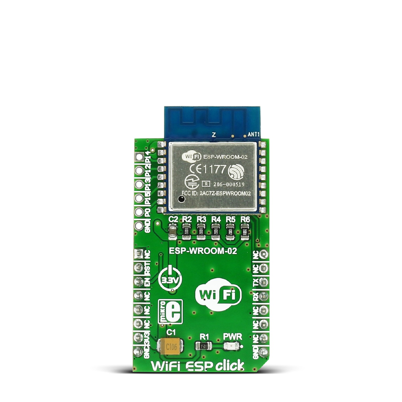
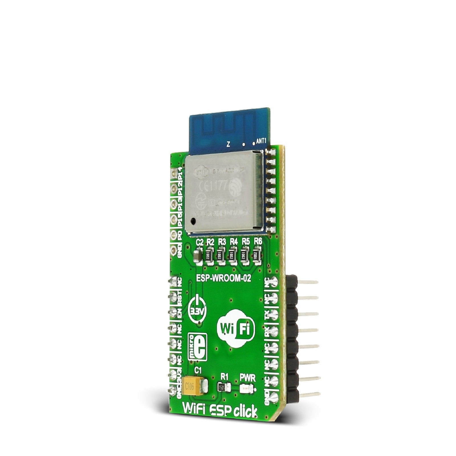
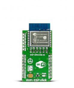
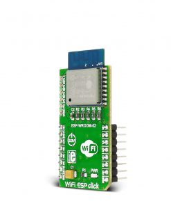
WiFi ESP Click is based on the ESP-WROOM-02, a fully integrated WiFi module from Espressif. It carries the well-known work-horse ESP8266EX, a highly integrated SoC solution that meets continuous demands for efficient power usage, compact design, and reliable performance in the industry. Besides the WiFi functionalities, ESP8266EX integrates an enhanced version of Tensilica’s L106 Diamond series 32-bit processor and on-chip SRAM, as well as antenna switches, RF balun, power amplifier, low noise receiver amplifier, filters, and power management modules. The module also includes 2MB of SPI flash to store a user program.
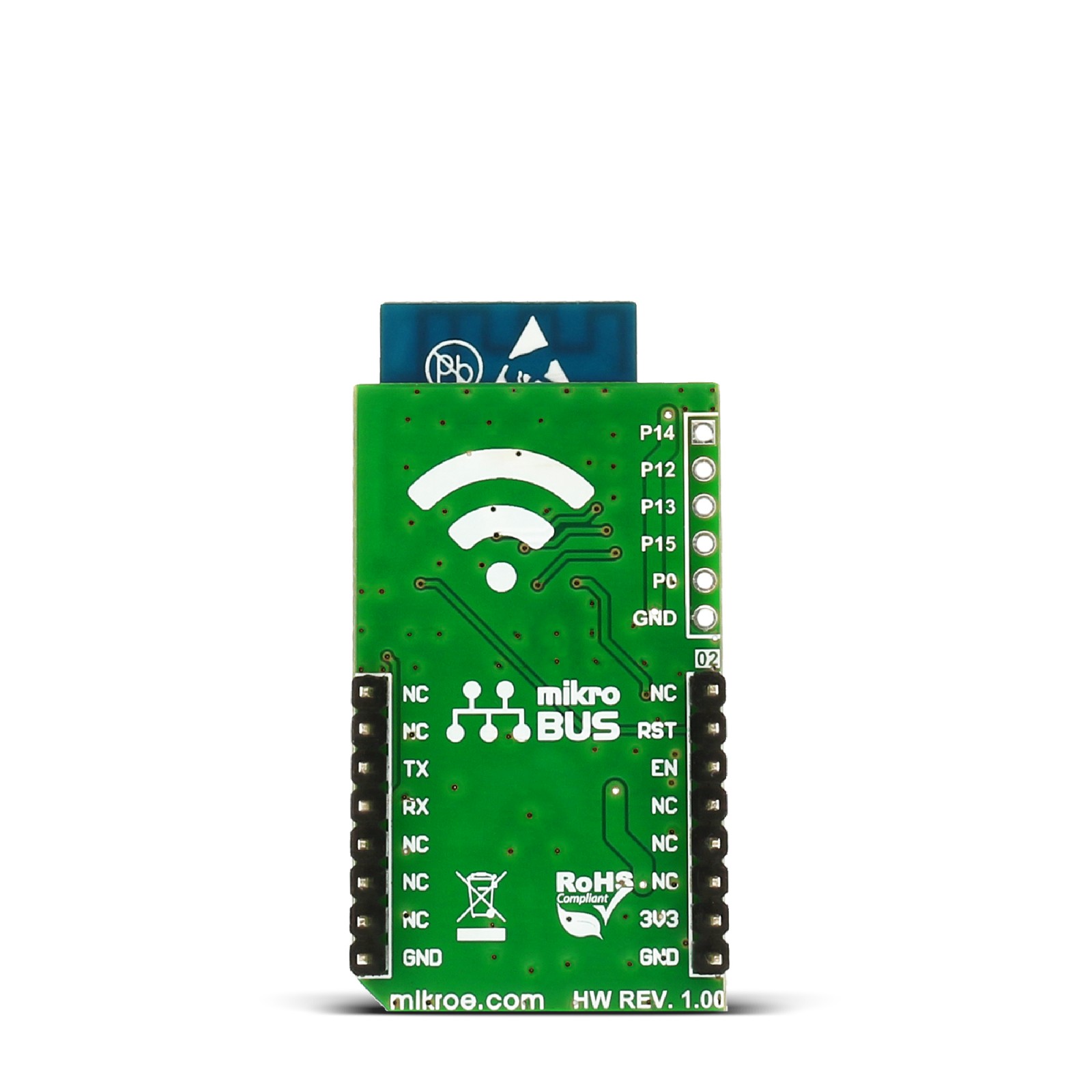
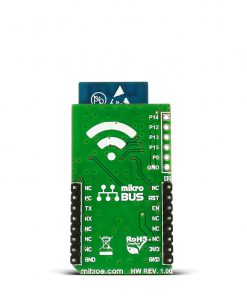
With the complete and self-contained WiFi networking capabilities, it can perform as either a standalone application (WROOM module itself) or the slave to an MCU host, which is the primary intention of the click board as a whole. So, this click board is applied to any microcontroller design as a WiFi adaptor through the UART interface (RX, TX lines on mikroBUS pin socket). The WiFi ESP Click comes with exposed 5 GPIOs of the module, which are part of the HSPI/GPIO interface of the module. The GPIO0 is used to enter the ESP8266EX’s UART download mode by shortening it with the GND just next to it. This way, you can upgrade the module’s firmware or upload a custom one.
WiFi ESP Click communicates with the host MCU using the UART interface as its default communication protocol at the 115200 baud rate. Besides standard UART RX and TX lines, the host MCU is also connected to the WiFi ESP Click with EN and RST lines. The first one turns off the module with a LOW logic state, while the latter is used to reset the ESP8266EX. You can also use the UART interface to communicate with the ESP-WROOM-O2 module by the AT commands set.
This Click board™ can only be operated with a 3.3V logic voltage level. The board must perform appropriate logic voltage level conversion before using MCUs with different logic levels. However, the Click board™ comes equipped with a library containing functions and an example code that can be used, as a reference, for further development.
Specifications
Type
WiFi
Applications
Create smart appliances, home automation systems, wireless data loggers, etc
On-board modules
ESP-WROOM-02 carries ESP8266EX highly integrated Wi-Fi SoC
Key Features
Protocols: IPv4, TCP/UDP/HTTP/FTP, 802.11 b/g/n standard, UART interface, 3.3V power supply
Interface
GPIO,UART
Feature
No ClickID
Compatibility
mikroBUS™
Click board size
M (42.9 x 25.4 mm)
Input Voltage
3.3V
Pinout diagram
This table shows how the pinout on WiFi ESP click corresponds to the pinout on the mikroBUS™ socket (the latter shown in the two middle columns).
Onboard settings and indicators
Label | Name | Default | Description |
---|---|---|---|
LD1 | PWR | – | Power LED Indicator |
WiFi ESP Click electrical specifications
Description | Min | Typ | Max | Unit |
---|---|---|---|---|
Supply Voltage | – | 3.3 | – | V |
Frequency Range | 2400 | – | 2483.5 | MHz |
Data Rate | – | – | 72.2 | Mbps |
Output Power | – | 20 | – | dBm |
Software Support
We provide a library for the Wifi ESP Click as well as a demo application (example), developed using MIKROE compilers. The demo can run on all the main MIKROE development boards.
Package can be downloaded/installed directly from NECTO Studio Package Manager(recommended way), downloaded from our LibStock™ or found on Mikroe github account.
Library Description
This library contains API for Wifi ESP Click driver.
Key functions
-
Sends AT command to the module.
-
Generic write function.
-
Generic read function.
Example Description
This example connects to the desired WiFi network and then creates web server on the IP address assigned to the click board. The user can connect to the server via web browser.
void application_task ( void )
{
app_error_flag = wifiesp_rsp_check( WIFIESP_RECEIVE );
Delay_ms( 100 );
if ( app_error_flag == APP_OK )
{
strcpy ( send_buf, link_id );
strcat ( send_buf, "," );
strcat ( send_buf, page_len );
str_cut_chr ( send_buf, ' ' );
wifiesp_send_cmd( &wifiesp, WIFIESP_SEND, send_buf );
app_error_flag = wifiesp_rsp_check( RSP_READY_FOR_SEND );
Delay_ms( 100 );
wifiesp_generic_write( &wifiesp, page, strlen( page ) );
app_error_flag = wifiesp_rsp_check( RSP_SEND_OK );
wifiesp_error_check( app_error_flag );
wifiesp_send_cmd( &wifiesp, WIFIESP_CLOSE, link_id );
app_error_flag = wifiesp_rsp_check( RSP_OK );
wifiesp_error_check( app_error_flag );
Delay_ms( 100 );
}
}
The full application code, and ready to use projects can be installed directly from NECTO Studio Package Manager(recommended way), downloaded from our LibStock™ or found on Mikroe github account.
Other Mikroe Libraries used in the example:
- MikroSDK.Board
- MikroSDK.Log
- Click.WifiEsp
Additional notes and informations
Depending on the development board you are using, you may need USB UART click, USB UART 2 Click or RS232 Click to connect to your PC, for development systems with no UART to USB interface available on the board. UART terminal is available in all MIKROE compilers.
mikroSDK
This Click board™ is supported with mikroSDK – MIKROE Software Development Kit. To ensure proper operation of mikroSDK compliant Click board™ demo applications, mikroSDK should be downloaded from the LibStock and installed for the compiler you are using.
For more information about mikroSDK, visit the official page.